
Femtosecond laser mode adjustable optical tweezers control device based on column vector light beam

A femtosecond laser and manipulation device technology, applied in optics, optical components, microscopes, etc., can solve problems such as thermal damage, achieve damage-free manipulation, improve capturing power, and avoid thermal damage.

Inactive Publication Date: 2014-07-16
HEILONGJIANG UNIV
View PDF3 Cites 13 Cited by
  • Summary
  • Abstract
  • Description
  • Claims
  • Application Information

AI Technical Summary

Problems solved by technology

[0004] In order to solve the problem that the traditional optical tweezers technology improves the capturing force of the optical tweezers by increasing the incident laser power, while the capturing force is increased, it will cause irreparable thermal damage to the manipulated object, and proposes a method based on cylindrical vector beam Femtosecond laser mode tunable optical tweezers manipulation device

Method used


Image

  • Femtosecond laser mode adjustable optical tweezers control device based on column vector light beam

Examples


specific Embodiment approach 1

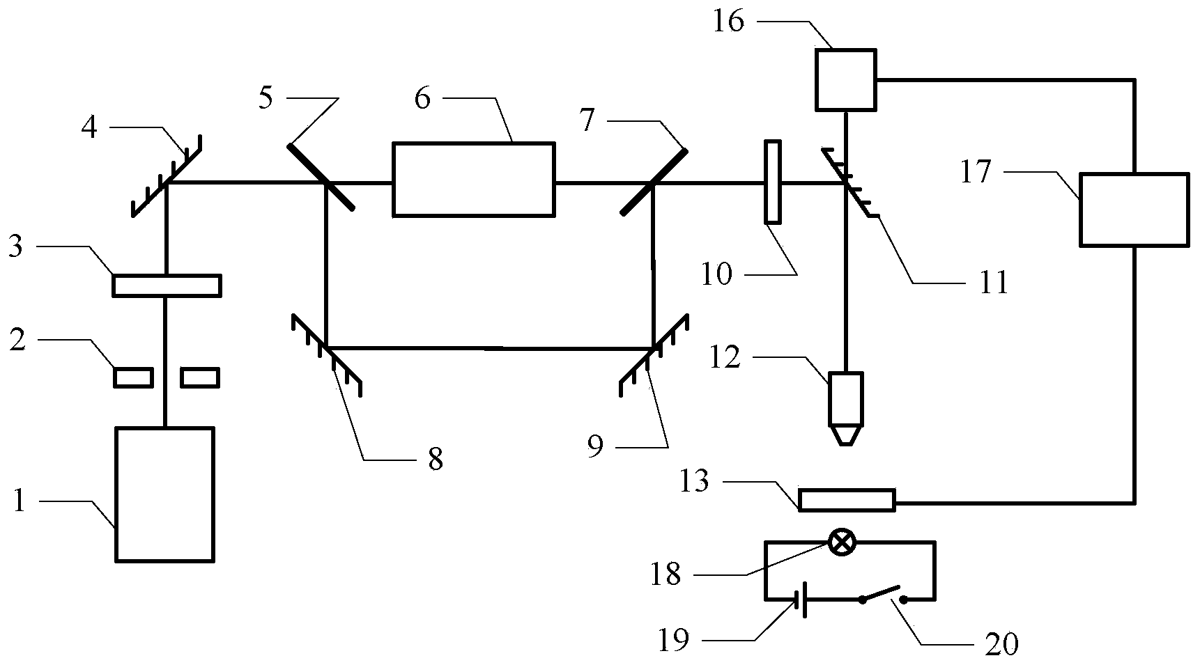
[0019] Specific implementation mode 1. Combination figure 1 Describe this specific embodiment. The difference between the femtosecond laser mode adjustable optical tweezers control device based on the cylindrical vector beam described in this specific embodiment is that it includes a femtosecond pulsed laser 1, an aperture 2, an attenuation plate 3, The first 800nm ​​total reflection mirror 4, the first beam splitter 5, the polarization converter 6, the second beam splitter 7, the second 800nm ​​total reflection mirror 8, the third 800nm ​​total reflection mirror 9, the shutter 10, the fourth 800nm ​​total reflection mirror mirror 11, microscope 12 and stage 13,

[0020] The pulsed laser light emitted by the femtosecond pulse laser 1 enters the attenuation plate 3 through the diaphragm 2, and the attenuation plate 3 attenuates the light intensity of the pulsed laser light, and then the pulsed laser light is incident on the first 800nm ​​total reflection mirror 4, and the first...

specific Embodiment approach 2

[0027] Embodiment 2. The difference between this embodiment and the femtosecond laser mode tunable optical tweezers control device based on cylindrical vector beam described in Embodiment 1 is that the femtosecond pulsed laser 1 is titanium-doped sapphire femto second laser with an output pulse repetition rate of 76 MHz and a pulse width of 120 femtoseconds.

specific Embodiment approach 3

[0028] Embodiment 3. The difference between this embodiment and the femtosecond laser mode tunable optical tweezers control device based on columnar vector beams described in Embodiment 1 is that the stage 13 is a three-dimensional micro-displacement platform.

[0029] The control accuracy of the three-dimensional linear excitation source of the stage 13 in this embodiment is 50 nm.


PUM


Abstract

The invention discloses a femtosecond laser mode adjustable optical tweezers control device based on a column vector light beam and relates to an optical tweezers technology for optical control particles and cells. The device solves the problem that the power of an incident laser needs to be increased to increase the trapping force of a pair of optical tweezers according to a traditional tweezers technology, but irretrievable thermal damage will be caused to a controlled object though the trapping force is increased. A seed light source provided with a femtosecond laser device is adjusted through a diaphragm, an attenuation piece and a first 800 nm holophote and is then split into a reflected laser and a transmitted laser through a first beam splitter, the transmitted laser is converted into the column vector light beam through a polarization converter, the column vector light beam enters a microscope after being adjusted by a second beam splitter, a shutter and a fourth 800 nm holophote, and the reflected laser enters the microscope after being adjusted by a second 800 nm holophote, a third 800 nm holophote, the second beam splitter, the shutter and the fourth 800 nm holophote. The device is suitable for research in the life science field.

Description

technical field [0001] The invention relates to optical tweezers technology for optically manipulating particles and cells. Background technique [0002] Since the emergence of optical tweezers technology, optical tweezers have been widely used in life sciences, medicine, physics, materials and nanoscience due to their non-contact and non-destructive manipulation of micro-nano-scale particles, and are considered to be the most ideal single molecule , single cell, particle, micro-nano device manipulation technology. [0003] Optical tweezers mostly use continuous laser and long pulse laser. Compared with continuous laser and long pulse laser, femtosecond laser pulse has extremely short pulse width, high peak power and time and space resolution, and can accurately detect Control action energy. At present, using a high repetition rate femtosecond laser as a light source can achieve stable capture of red blood cells, white blood cells, viruses, polystyrene microspheres, etc. ...

Claims


Application Information

Patent Timeline
IPC IPC(8): G02B21/32G02B27/28G21K1/00
Inventor 冉玲苓高扬王积翔孔德贵吴文智
Owner HEILONGJIANG UNIV
Learn More