Compact large-framework-angle conformal optical system

An optical system and frame angle technology, applied in the field of optical systems, can solve problems such as the inability to achieve good imaging of a large target field of view without vignetting, limit the development of conformal optics technology, and cannot correct conformal window astigmatism and coma. Achieve the effect of simple structure, wide range of uses and easy installation and adjustment

Inactive Publication Date: 2014-07-16
CHANGCHUN INST OF OPTICS FINE MECHANICS & PHYSICS CHINESE ACAD OF SCI
View PDF6 Cites 8 Cited by
  • Summary
  • Abstract
  • Description
  • Claims
  • Application Information

AI Technical Summary

Problems solved by technology

[0004] Although the above methods can correct the aberration of the conformal window within a certain angle range (less than 50°), they cannot correct the astigmatism and coma caused by the...

Method used


Image

  • Compact large-framework-angle conformal optical system
  • Compact large-framework-angle conformal optical system
  • Compact large-framework-angle conformal optical system

Examples


Embodiment Construction

[0025] The present invention will be described in further detail below in conjunction with the accompanying drawings and specific embodiments.

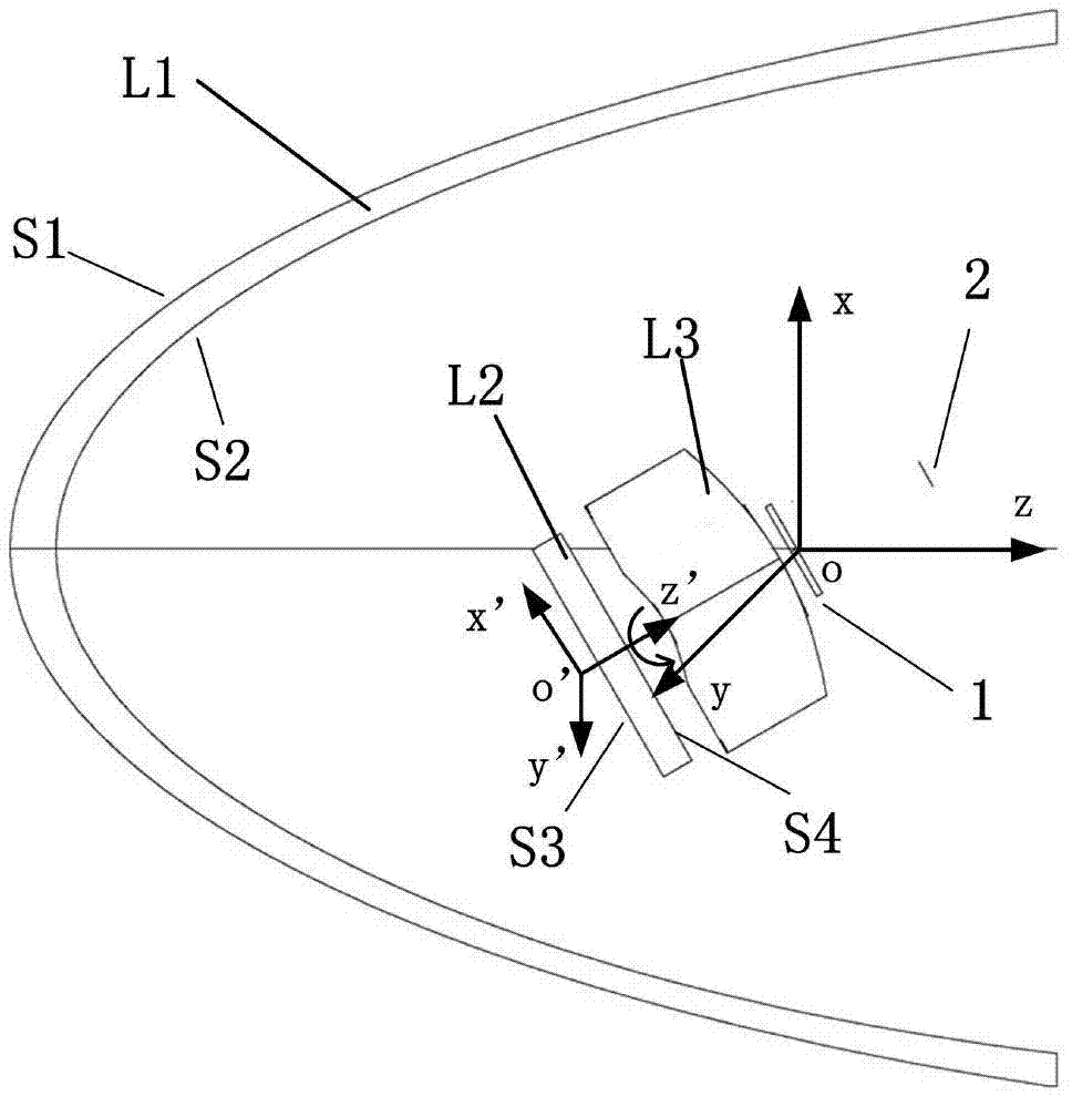
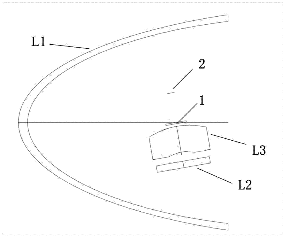
[0026] like figure 1 and figure 2 As shown, the compact large frame angle conformal optical system of the present invention includes a fairing L1, a cylindrical correction lens L2, an imaging lens group L3 and a diaphragm 1, and the cylindrical correction lens L2 is located behind the conformal optical window for The light aberration of the dome is corrected, the imaging lens group L3 is located behind the cylindrical correction lens L2, and the diaphragm 1 is located behind the imaging lens group L3. The cylindrical correction lens L2, the imaging lens group L3, the diaphragm 1 and the detector 2 as a whole can rotate around the x-axis and the y-axis around a point o on the optical axis of the fairing L1, and the angle with the z-axis is α, at the same time, the cylindrical correction lens L2 can also rotate around its own optical...


PUM


Abstract

The invention provides a compact large-framework-angle conformal optical system. After light passes through a rectifying cover and reaches a cylindrical-surface correcting lens, the phase position of the light can be corrected through the cylindrical-surface correcting lens, the light passing through the cylindrical-surface correcting lens is emitted out through an imaging lens set, and the light emitted out through the imaging lens set is subjected to eco-planar imaging on a detector after passing through a diaphragm; the cylindrical-surface correcting lens, the imaging lens set and the diaphragm rotate around a rotating center of an optical axis of the rectifying cover, an alpha angle is formed between the cylindrical-surface correcting lens and the z axis, as well as between the imaging lens set and the z axis, and between the diaphragm rotate and the z axis, meanwhile, the cylindrical-surface correcting lens rotates around the optical axis z' of itself, the rotating angle in the clockwise direction is beta, beta=f(alpha), and when different target view fields are imaged through the optical system and the optical system respectively rotates at the angle of alpha and at the angle of beta, complete imaging of objects in the target view fields is achieved. The requirement for performing detection and tracking objectives within the range of a large framework angle (>=100 degrees) can be met by the system, and the optical system can be extensively used.

Description

technical field [0001] The invention belongs to the field of optical systems, and in particular relates to a compact large frame angle conformal optical system. Background technique [0002] At present, traditional aircraft fairings are generally spherical, so the design of the rear imaging optical system is relatively simple, but when the speed of the aircraft reaches several Machs, due to aerodynamic heating, the temperature will stagnate at the top and edge of the aircraft fairing. The image in the field of view forms interference noise, which can lead to failure to identify the target in severe cases. In addition, the air resistance of the spherical fairing is very large at high speeds, which seriously limits the speed and range of the aircraft. The conformal aircraft fairing uses a streamlined curved surface instead of a traditional spherical surface, including quadric surfaces, aspheric surfaces and other various geometric surfaces that can improve flight performance....

Claims


Application Information

Patent Timeline
IPC IPC(8): G02B27/00G02B17/08G02B3/02
Inventor 虞林瑶魏群张天翼王超朱瑞飞贾宏光
Owner CHANGCHUN INST OF OPTICS FINE MECHANICS & PHYSICS CHINESE ACAD OF SCI
Why Eureka
Try Eureka