Novel method for manual viscosity control

A manual control and new method technology, applied in the direction of viscosity control, non-electric variable control, control/adjustment system, etc., can solve the problem of high equipment investment cost and later equipment maintenance cost, the influence of the accuracy of viscosity correction value, and the difficulty of vibrating viscometer In case of failure and other problems, the effect of improving control stability, simple installation and convenient operation is achieved.

Active Publication Date: 2014-07-16
浙江佳人新材料有限公司
View PDF4 Cites 2 Cited by
  • Summary
  • Abstract
  • Description
  • Claims
  • Application Information

AI Technical Summary

Problems solved by technology

Its disadvantages are: 1. The oscillating viscometer is easily disturbed by some external factors such as temperature and pressure changes, and it is prone to failure, which will also affect the accuracy of the subsequent viscosity correction value
2. In

Method used


Image

  • Novel method for manual viscosity control
  • Novel method for manual viscosity control

Examples


Embodiment 1

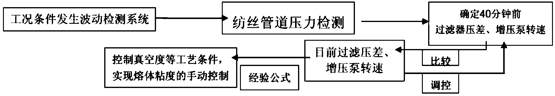
[0023] A new method for manual viscosity control is used to guide melt viscosity control when production conditions change. Such as figure 1 The specific control process shown includes: the production condition fluctuation detection system finds abnormal production conditions → the spinning pipeline pressure detection system detects the melt pressure in the pipeline → calculates the filter pressure difference and booster pump speed 40 minutes ago → Convert the melt viscosity drop through the pressure conversion formula 1 and the correction formula 2 of the actual viscosity change → use the converted melt viscosity drop as a production guide to adjust the vacuum degree and other process conditions → realize manual control of the melt viscosity.

[0024] The specific operation method is:

[0025] (1) When the production condition fluctuates, pass the formula 1 through the spinning pipeline pressure detection system:

[0026] P=ΔPr+Pg+ΔPf

[0027] Infer the filter pressure dif...

Embodiment 2

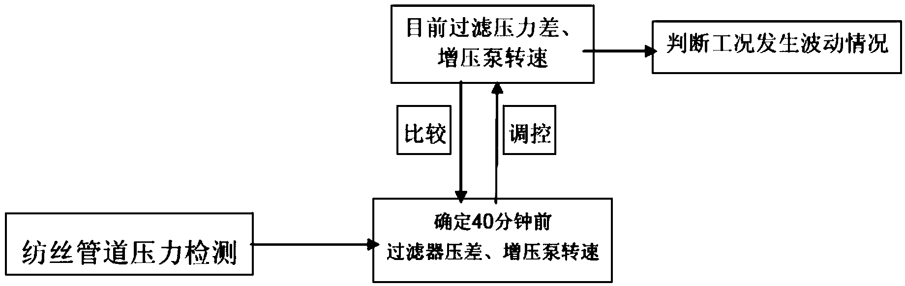
[0033] A new method for manual viscosity control, used in judging changes in production conditions. Such as figure 2 The specific control process shown includes: the spinning pipeline pressure detection system measures the melt pressure in the pipeline → calculates the filter pressure difference and booster pump speed 40 minutes ago and compares it with the current filter pressure difference and booster pump speed → Judging changes in production conditions.

[0034] The specific operation method is:

[0035] (1) The pressure difference of the filter and the speed of the booster pump 40 minutes ago can be calculated by measuring the melt pressure in the pipeline through the pressure detection system of the spinning pipeline.

[0036] (2) Compare the differential pressure of the filter and the rotational speed of the booster pump 40 minutes ago calculated through step (1) with the differential pressure of the filter and the rotational speed of the booster pump at present.

...


PUM


Abstract

The invention relates to a novel method for manual viscosity control. The novel method for the manual viscosity control is used for guiding melt viscosity control when production conditions are changed. The novel method for the manual viscosity control concretely comprises the following concrete control steps that abnormal production conditions are found; melt pressure in a pipeline is measured through a spinning pipeline pressure measurement system; the pressure difference of a filter and the rotational speed of a boost pump before 40 minutes are deduced; melt viscosity drop is calculated in a conversion mode through a pressure conversion formula I and a modification formula II of an actual viscosity change; the melt viscosity drop which is calculated in the conversion mode is used as production instructions to adjust the vacuum degree and other process conditions; manual control over melt viscosity is achieved. The novel method for the manual viscosity control has the advantages that the melt viscosity control is achieved by the adoption of the control method; the melt pressure change is measured on line, the melt viscosity drop is calculated in the conversion mode through the empirical formulas, and therefore the control over the melt viscosity is finally achieved; in this way, the novel method further has the advantages that equipment investment costs are low, installation is simple, and operation is convenient.

Description

【Technical field】 [0001] The invention relates to the field of quality control of polyester products, in particular to a new method for manual viscosity control. 【Background technique】 [0002] One of the key indicators of polyester product quality is viscosity, which is currently the most important quality control parameter in polyester fiber production. The quality of viscosity control largely determines the quality of the final product. The current commonly used viscosity testing method generally uses a viscometer for on-line automatic control, but because the equipment is relatively precise and susceptible to interference from external factors such as temperature and pressure changes, it is prone to failure. At this time, manual control becomes a difficult problem. According to the conventional manual control method, its CPK is generally only about 1.03, and the stability can only barely meet the production needs, and there is a risk of product degradation due to contro...

Claims


Application Information

Patent Timeline
IPC IPC(8): G05D24/02G01N11/00
Inventor 富洪志肖国枝钟伟祖顾日强
Owner 浙江佳人新材料有限公司
Why Eureka
Try Eureka