Device and method for winding or unwinding cuff

A technology of cuff and volume control, applied in vascular assessment, cardiac catheterization, etc., to achieve the effect of easy disassembly, improved durability, and durability

Active Publication Date: 2014-07-23
BEIJING CHIOY MEDICAL TECH CO LTD
View PDF7 Cites 15 Cited by
  • Summary
  • Abstract
  • Description
  • Claims
  • Application Information

AI Technical Summary

Problems solved by technology

It solves the problem of automatically tightening or loosening the cuff in blood pressure measurement, and how to balance the force on the arm during the measurement process, and improves the accuracy and comfort of the measurement

Method used


Image

  • Device and method for winding or unwinding cuff
  • Device and method for winding or unwinding cuff
  • Device and method for winding or unwinding cuff

Examples


no. 1 example

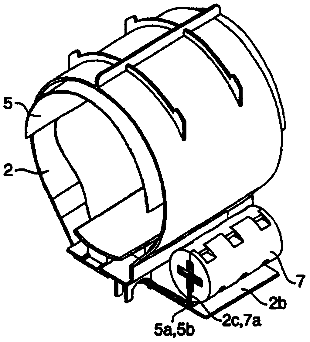
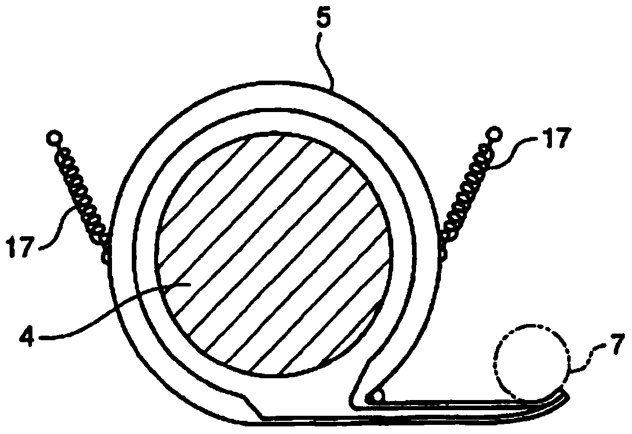
[0063] First refer to Figure 5 to Figure 9 A device for tightening or loosening a cuff according to a first embodiment of the present invention will be described. Figure 5 It is a front view of the device for tightening or loosening the cuff according to the first embodiment of the present invention, that is, a view of the device for tightening or loosening the cuff seen from the direction of the subject. Figure 6 It is a sectional view of the main shaft of the first embodiment viewed from the left side of the subject. Figure 7 It is a side view of the take-up mechanism of the first embodiment viewed from the left side of the subject. Figure 8 It is a schematic diagram of the relationship between the sleeve and the slide rail of the first embodiment. Figure 9 It is a schematic diagram of the kinematic relationship between the main shaft and the sleeve in the first embodiment.

[0064] Such as Figure 5 As shown, the device for tightening or loosening a cuff according...

no. 2 example

[0092] now refer to Figure 12 and 13 A device for tightening or loosening a cuff according to a second embodiment will be described. Figure 12 is a front view of the device for tightening or loosening the cuff according to the second embodiment. Figure 13 It is a side view of the device for tightening or loosening the cuff viewed from the right side of the subject according to the second embodiment.

[0093] The device for tightening or loosening the cuff according to the second embodiment differs from the device according to the first embodiment in that it includes a base 501 and a guide rail 514 .

[0094] The base 501 is used to support the entire main body, and is connected with the main body through a damping shaft 516 . The main body can adjust the angle through the damping shaft 516, such as Figure 13 shown. When the angle of the main body is adjusted, the angle of the base 501 does not change, and the damping shaft 516 can maintain any angle within the adjusta...

no. 3 example

[0100] Figure 14 is a side view of the device for tightening or loosening the cuff according to the third embodiment. Since the device is mainly aimed at the upper arm, if the arm is placed incorrectly, it will cause differences in measurement results, so a monitoring switch 517 is set at one end of the sleeve. Only when the monitoring switch 517 is correctly pressed, the hand placement action is considered correct.

[0101] Alternatively, although in the above embodiments a combination of a motor and a clutch is used to perform tightening and loosening movements, a stepping motor is also used instead of a motor+clutch. Driven by a stepper motor to rotate and brake and hold. Other modes with power and braking functions can also be used to replace the motor+clutch mode.


PUM


Abstract

The invention provides a device and method for winding or unwinding a cuff. The device for winding or unwinding the cuff comprises a winding mechanism, the cuff attached to the inner portion of the winding mechanism and a control part used for controlling the winding mechanism to carry out winding or unwinding. The device is characterized in that the winding mechanism is made to carry out winding or unwinding in a barrel shape through the control part to wind or unwind the cuff in the winding mechanism, so that the cross section area of the winding mechanism is changed.

Description

technical field [0001] The invention relates to the field of medical devices, more specifically, to a device and method for tightening or loosening a cuff. Background technique [0002] In the process of measuring blood pressure by the oscillometric method, it is necessary to put a cuff on the corresponding part to be measured. A cuff is an accessory used in blood pressure measurement to wrap around a limb and block blood flow by inflating it. figure 1 is a schematic diagram of a cuff. Such as figure 1 As shown, the cuff is made up of a soft packaging 101 , an air bag (not shown) placed in the soft packaging, an inflation tube 102 , a locking or adhesive component 103 , and a joint / interface 104 . [0003] Different body thicknesses and different cuff methods will cause changes in the inflatable volume of the airbag. The change of the inflatable volume of the airbag has a great influence on the strength of the measured signal, so the measurement result is greatly affecte...

Claims


Application Information

Patent Timeline
Patent Type & Authority Applications(China)
IPC IPC(8): A61B5/022
Inventor 徐亮禹潘学东傅勇冯磊
Owner BEIJING CHIOY MEDICAL TECH CO LTD
Why Eureka
Try Eureka