[0025] The present invention will be further described in detail below in conjunction with the drawings and specific embodiments:
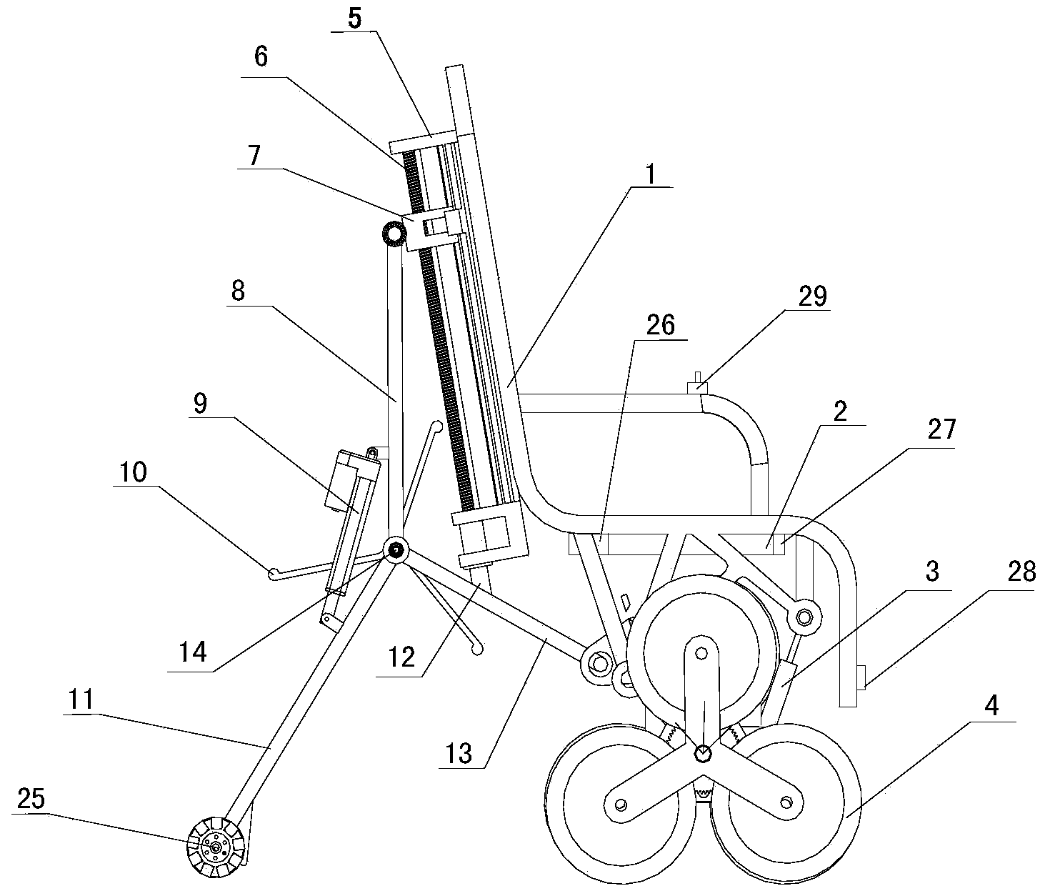
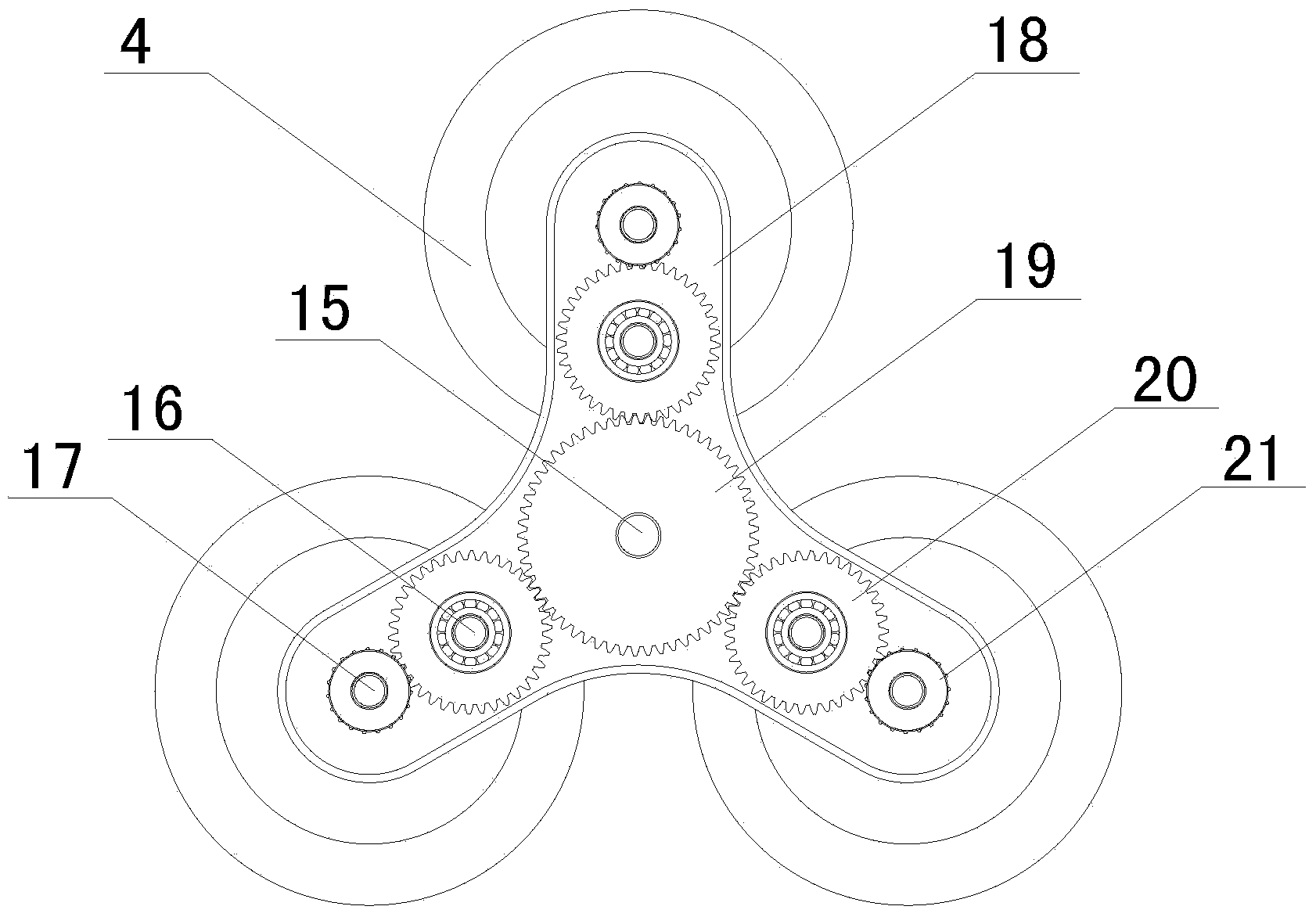
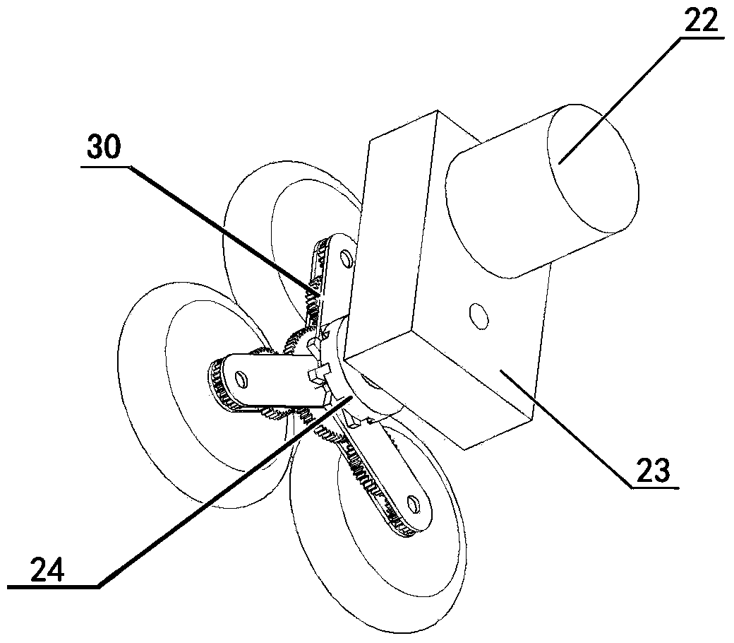
[0026] Such as Figure 1 ~ Figure 4 As shown, an under-driven adaptive stair climbing wheelchair includes a chair frame body 1, a battery 2, a balancing mechanism, a driving system, and a control system. The battery 2 is fixed to the lower part of the seat of the chair frame body 1;
[0027] The drive system includes a gearbox 23, a main motor 22, and an under-driven gear train 30. The drive system is provided with a left and right set on the seat frame body 1, which can be turned by the rotation difference between the left and right sets of drive systems. The rear part of the housing of the gearbox 23 is hinged to the lower part of the seat frame body 1, the front part of the housing of the gearbox 23 is hinged to one end of the shock absorber 3, and the other end of the shock absorber 3 is hinged to the lower part of the seat frame body 1. The main motor 22 is fixed on the housing of the gearbox 23, and the power output end of the main motor 22 is fixedly connected with the power input end of the gearbox 23. The under-driven gear train in this embodiment is a three-arm star The gear train, including the gear box 18, the wheel carrier shaft 15, the middle axle 16, the small axle 17 and the wheels 4, can also be manufactured as a four-arm star gear train. The advantage of the three-arm star gear train is that it can cross higher The advantage of the four-arm star gear system is that it is more stable when crossing obstacles. Different gear trains can be manufactured according to different customer needs during production. The under-driven gear train 30 includes a gear box 18, a wheel carrier shaft 15, and The middle shaft 16, the small shaft 17, and the wheels 4. The wheel carrier shaft 15 is connected to the power output end of the gearbox 23, the wheel carrier shaft 15 is arranged on the gear box 18 through a bearing, and the wheel carrier shaft 15 is fixed with Big gear 19; The middle shaft 16 and the small shaft 17 are fixed in the gear box 18, the middle gear 20 is movably sleeved on the middle shaft 16, and the small gear 21 is movably sleeved on the small shaft 17. The small gear 21, The middle gear 20 and the large gear 19 are both arranged in the gear box 18; the wheels 4 and the small gears 21 have the same number, and are fixedly connected to the small gear 21, the large gear 19 meshes with the middle gear 20, and the middle gear 20 and The pinion gear 21 is meshed. An electromagnetic clutch 24 is also provided between the gearbox 23 and the under-driven gear train 30. The active end 31 of the electromagnetic clutch is fixedly sleeved on the wheel carrier shaft 15 of the under-driven gear train 30. The moving end 31 is fixed on the gear box 18. When the electromagnetic clutch 24 is engaged, the gear box 18 and the wheel carrier shaft 15 move simultaneously.
[0028] The balance mechanism includes a screw bracket 5, an upper frame 8, a lower frame 13, and a tail frame 11. The screw bracket is fixed on the back of the chair frame body 1, and a screw 6 is provided on the screw bracket 5. The housing of the screw motor 9 is fixed at the rear of the frame body, and the power output end of the screw motor 9 is fixedly connected with the screw 6; the upper end of the upper frame 8 is hinged with a slider 7 with threaded holes, and the slider 7 is connected to the The screw 6 is matched, the lower end of the lower frame 13 is hinged to the lower part of the chair frame body 1, the upper end of the lower frame 13 and the lower end of the upper frame 8 and the upper end of the tail frame 11 are hinged on the frame shaft 14, and the tail frame 14 A universal wheel 25 is provided at the lower end of the frame. A one-way rotating support frame 10 is installed on the frame shaft 14, which can provide a part of the supporting force for the chair frame body 1 when going up and down stairs; one end of the linear motor 9 is hinged on the upper frame 8 , The other end of the linear motor 9 is hinged with the tail frame 11;
[0029] The control system includes an angle sensor 27, a controller 26, a distance sensor 28, and an operating handle 29. In this embodiment, the controller is a PLC and an angle sensor. The operating handle 29 is provided on the chair frame body 1, and the PLC and The angle sensor 27 is located at the lower part of the seat of the chair frame body 1, and the distance sensor 28 is located at the lower front part of the chair frame body 1. The signal input terminals of the PLC are respectively connected with the angle sensor 27, the distance sensor 28 and the operating handle 29. The signal output terminals are respectively connected to the main motor 22, the linear motor 9, the electromagnetic sensor 24 and the screw motor 12; the battery is respectively connected to the angle sensor 27, the distance sensor 28, the electromagnetic sensor, the operating handle 29, the main motor 22, and the linear motor 9 and the screw motor 12 are connected.
[0030] In this embodiment, the angle sensor model is MPU6050, the distance sensor model is E18-D80NK, the PLC uses Siemens s7-200, and the operating handle model is XB222.
[0031] The operation process of the under-driven gear train in this embodiment is as follows:
[0032] When the ground is level, the main motor 22 provides power. After the gearbox 23 is shifted, the power is transmitted to the wheel carrier shaft 15. The wheel carrier shaft 15 drives the large gear 19 to operate. The large gear 19 drives the middle gear 20 and further drives the small gear 21 and The rotation of the wheel 4 completes the forward motion. If the PLC controls the left and right sets of main motors 22 to provide the same speed, the two sets of wheel trains move at the same speed, and the wheelchair moves straight. If the PLC controls the left and right sets of drive systems to provide different speeds, the speed of the wheels 4 Different, you can realize the turning action.
[0033] When the wheel 4 encounters an obstacle, the wheel 4 will stop rotating, so the small gear 21 and the middle gear 20 will also stop rotating. The torque of the large gear 19 against the middle gear 20 will cause the entire gear train to flip forward and cross the obstacle. , When the wheelchair is on the stairs, the previous steps will be repeated many times, thus further climbing the stairs. If the electromagnetic clutch 24 is in the pull-in state, the wheel 4 will also stop rotating, and the wheel carrier shaft 15 will rotate forward at the same time as the gear box 18 and cross the obstacle.
[0034] The operation process of the balancing mechanism in this embodiment is as follows:
[0035] When the seat frame body 1 is tilted forward, the angle sensor 27 will send a signal to the PLC, and the PLC will send a control signal to the lead screw motor 12 and the linear motor 9 to move the slider 7 upwards and the linear motor 9 to contract, so that the tail frame 11 lifts To restore the balance of the chair frame body 1.
[0036] When the seat frame body 1 is tilted backward, the angle sensor 27 will send a signal to the PLC to make the PLC send control signals to the lead screw motor 12 and the linear motor 9, so that the slider 7 moves downward and the linear motor 9 extends, so the tail frame 11 descends, finally restoring the balance of the chair frame body 1.
[0037] Combine the control function of the control system, the working principle of the under-driven gear train and the balance mechanism, such as Figure 5 ~ Figure 6 As shown, the working steps of going up and down stairs in this embodiment are as follows:
[0038] When going up the stairs, select the upstairs mode and control the operating handle 29 to move forward. At this time, the angle sensor 27 will send a signal to the PLC. If the angle sensor 27 is in the horizontal state, the PLC will control the main motor 22 to run and the wheel train moves forward. When starting to go up the stairs, the chair frame body 1 will tilt back, the angle sensor 27 will send a signal to the PLC, the PLC will control the linear motor 9 to extend, the screw motor 12 reverses to make the slider 7 move down, so that the chair frame body 1 Lean forward and continuously adjust the posture to keep the main body 1 of the chair frame balanced.
[0039] When going down the stairs, select the downstairs mode and control the operating handle 29 to move forward. At this time, the PLC will control the electromagnetic clutch 24 so that the active end 31 and the driven end 32 of the electromagnetic clutch are attracted, so that the wheel carrier shaft 15 and the gear box 18 are at the same time Movement helps the gear train to run smoothly on the stairs. The angle sensor 27 will send a signal to the PLC. If the angle sensor 27 is in a horizontal state, the PLC will control the main motor 22 to run, and the gear train will move forward when it starts to descend the stairs. , The chair frame body 1 will tilt forward, the angle sensor 27 will send a signal to the PLC, the PLC will control the linear motor 9 to contract, the screw motor 12 will rotate forward to move the slider 7 upward, so that the chair frame body 1 will tilt backward, and Constantly adjust the posture to keep the main body 1 of the chair frame running in balance.
[0040] After the upstairs or downstairs action is completed, and the leveling state is entered, the PLC will automatically determine the posture of the chair frame body 1 according to the signal sent by the angle sensor 27, adjust the levelness, and continue to move forward.
[0041] If there is a high drop ahead, such as a cliff or a deep trench, a sewer opening without a manhole cover, etc., the distance sensor 28 detects that there is a long distance between the front and the bottom, and it will send a signal to the PLC, and the PLC will stop the main motor 22. Run and issue a warning.