Pipe end heading machine

A pier head machine and pipe end technology, which is applied in the field of pier head machines, can solve the problems of vertical force in clamping, horizontal force in the pier head cylinder, breakage, uneven force on the frame, etc.

Active Publication Date: 2014-07-23
WEICHAI HEAVY MACHINERY
View PDF6 Cites 3 Cited by
  • Summary
  • Abstract
  • Description
  • Claims
  • Application Information

AI Technical Summary

Problems solved by technology

[0005] However, it can be seen from the above-mentioned structure that the workpiece of the pipe-end piercing machine is clamped by a vertically arranged compression cylinder, and when working, the piercing force is along the axial direction of the pipe fitting 6, that is, during the piercing process Among them, the guide rod of the compression cylinder (between the upper die 8 and the frame 1) is subject to a large tangential force, which is prone to breakage; in addition, when the cylinder is clamped, there is a vertical force, and the pier head cylinder There is force in the horizontal direction, the force on the frame is uneven, and the strength requirements for the workbench are relatively high

Method used


Image

  • Pipe end heading machine
  • Pipe end heading machine
  • Pipe end heading machine

Examples


Embodiment Construction

[0027] The core of the present invention is to provide a pipe end pier head machine, the force generated by the pier head is the same as the compacting direction of the workpiece, which avoids the breakage of the guide rod in the compression cylinder, thereby improving the performance of the pipe end pier head machine. performance and prolong its service life.

[0028] In order to enable those skilled in the art to better understand the solution of the present invention, the present invention will be further described in detail below in conjunction with the accompanying drawings and specific embodiments.

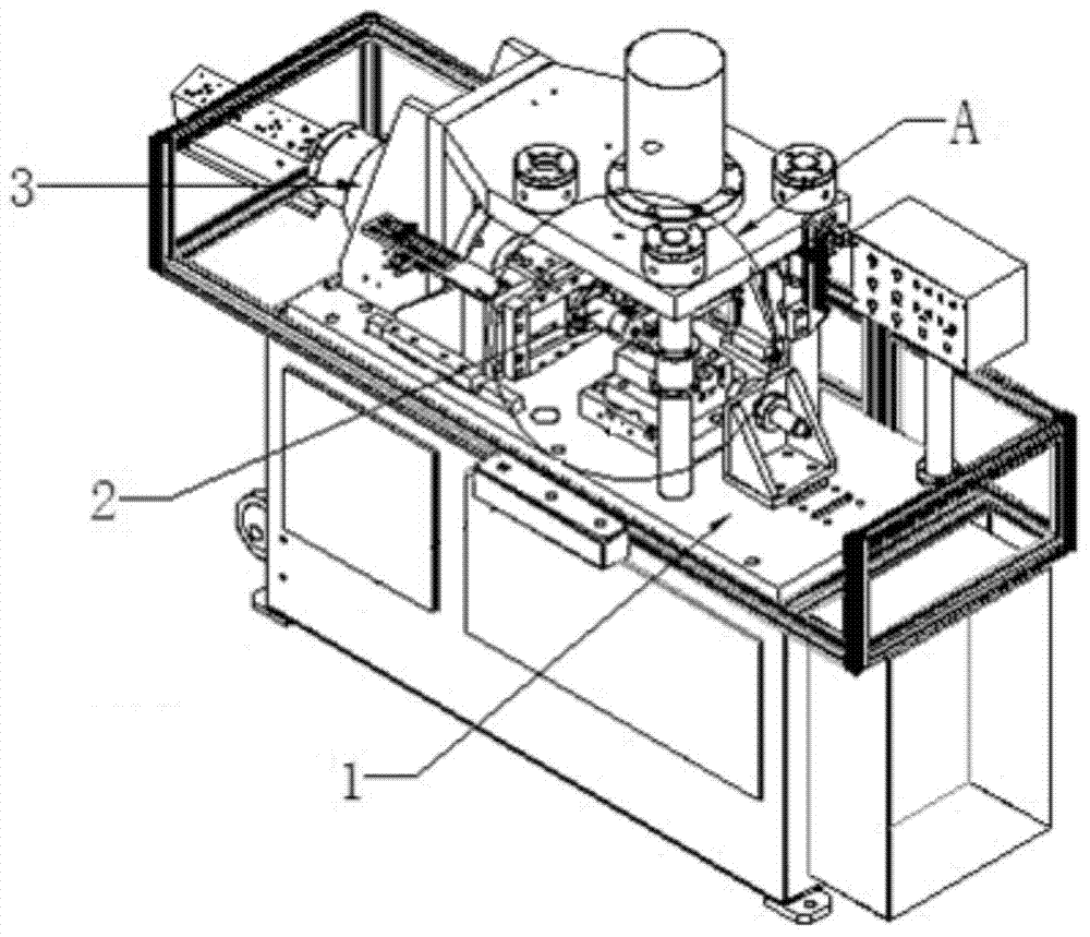
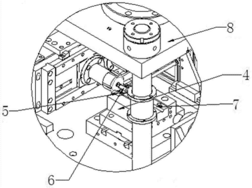
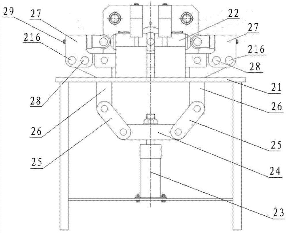
[0029] Please refer to image 3 , image 3 It is a structural schematic diagram of a specific embodiment of the pipe end heading machine provided by the present invention.

[0030] In a specific embodiment, the pipe end heading machine provided by the present invention includes a workbench 21 and a die 22 arranged on the workbench 21, wherein the die 22 includes a first di...


PUM


Abstract

The invention discloses a pipe end heading machine. The pipe end heading machine comprises a machine frame and a pressing die arranged on the machine frame. Specifically, the pressing die can comprise a clamping block used for clamping a workpiece, and a clamping block seat used for installing the clamping block. The pressing die comprises a first pressing die body and a second pressing die body, wherein the first pressing die body and the second pressing die body perform clamping through a power element. The first pressing die body and the second pressing die body are transversely arranged along the machine frame, and the ends, away from each other, of the two pressing die bodies are in transmission connection with the power element through a clamping mechanism. Thus, in heading work, a heading oil cylinder (or an air cylinder) transversely acts on the pressing die, meanwhile, the pressing directions of the first pressing die body and the second pressing die body are transverse of the machine frame, the direction of action force generated by heading and the pressing direction of the workpiece are the same, breaking of a guide rod in a pressing cylinder is avoided, and therefore the working performance of the pipe end heading machine is improved, and the service life of the pipe heading machine is prolonged.

Description

technical field [0001] The invention relates to the technical field of mechanical processing equipment, in particular to a piercing machine for forming the ends of pipe fittings. Background technique [0002] In order to improve the processing efficiency, the end forming operation of the pipe fittings is mostly completed by the pipe end pier machine at present. [0003] Please refer to figure 1 and figure 2 , figure 1 It is a schematic structural diagram of a typical pipe end pier; figure 2 for figure 1 Enlarged view of part A in Fig. [0004] As shown in the figure, a typical pier head machine includes a machine base 1, on which a pier head mold 2 and an oil cylinder 3 that can drive the pier head mold to move forward and backward are arranged, and a fixed lower mold 4 is arranged in front of the pier head mold 2 , a sliding lower die 5 that can slide back and forth in the fixed lower die 4 is provided in the fixed lower die 4 and at a position opposite to the pier ...

Claims


Application Information

Patent Timeline
Patent Type & Authority Applications(China)
IPC IPC(8): B21D19/08
Inventor 高德成孙国明崔振国刘建新周兆亮杜明华
Owner WEICHAI HEAVY MACHINERY
Why Eureka
Try Eureka