Method for drying silt or sludge
A sludge drying and sludge technology, which is applied in the direction of dehydration/drying/concentrated sludge treatment, etc., can solve the problems of not reaching the sludge content rate, etc., achieve an increase in the sludge content rate, good drying effect, and reduce storage yards Effect
- Summary
- Abstract
- Description
- Claims
- Application Information
AI Technical Summary
Problems solved by technology
Method used
Image

Examples
Embodiment 1
[0018] One end of the drainage board 1 is connected to the vacuum pipe network 2, and the other end exposes the silt surface.
[0019] In this embodiment, the volume of the drying pool is 10m 3 , the specific steps are as follows:
[0020] (1) Pre-treatment: transport the sludge or sludge to be treated to the drying tank for preliminary precipitation;
[0021] (2) Setting of drainage boards: Insert several drainage boards in the silt or sludge obtained in step (1). A drainage channel is formed between the water-permeable layer and the drainage groove; the end of the drainage groove has a through first port and a second port; when the drainage board is inserted, the drainage groove is located in the silt or sludge, and the end of the drainage groove The first port and the second port protrude from the sludge or the surface of the sludge; and the first port or / and the second port are connected with a vacuum pipe network.
[0022] The vacuum pipe network includes a first vacuu...
Embodiment 2
[0030] One end of the drainage board 1 is connected with the vacuum pipe network 2, and the other end is connected with the vacuum pipe network 3, and the connected vacuum pipe network 3 communicates with nature.
[0031] In this embodiment, the volume of the drying pool is 10m 3 , the specific steps are as follows:
[0032] (1) Pre-treatment: transport the sludge or sludge to be treated to the drying tank for preliminary precipitation;
[0033] (2) Setting of drainage boards: Insert several drainage boards in the silt or sludge obtained in step (1). A drainage channel is formed between the water-permeable layer and the drainage groove; the end of the drainage groove has a through first port and a second port; when the drainage board is inserted, the drainage groove is located in the silt or sludge, and the end of the drainage groove The first port and the second port protrude from the sludge or the surface of the sludge; and the first port or / and the second port are connect...
Embodiment 3
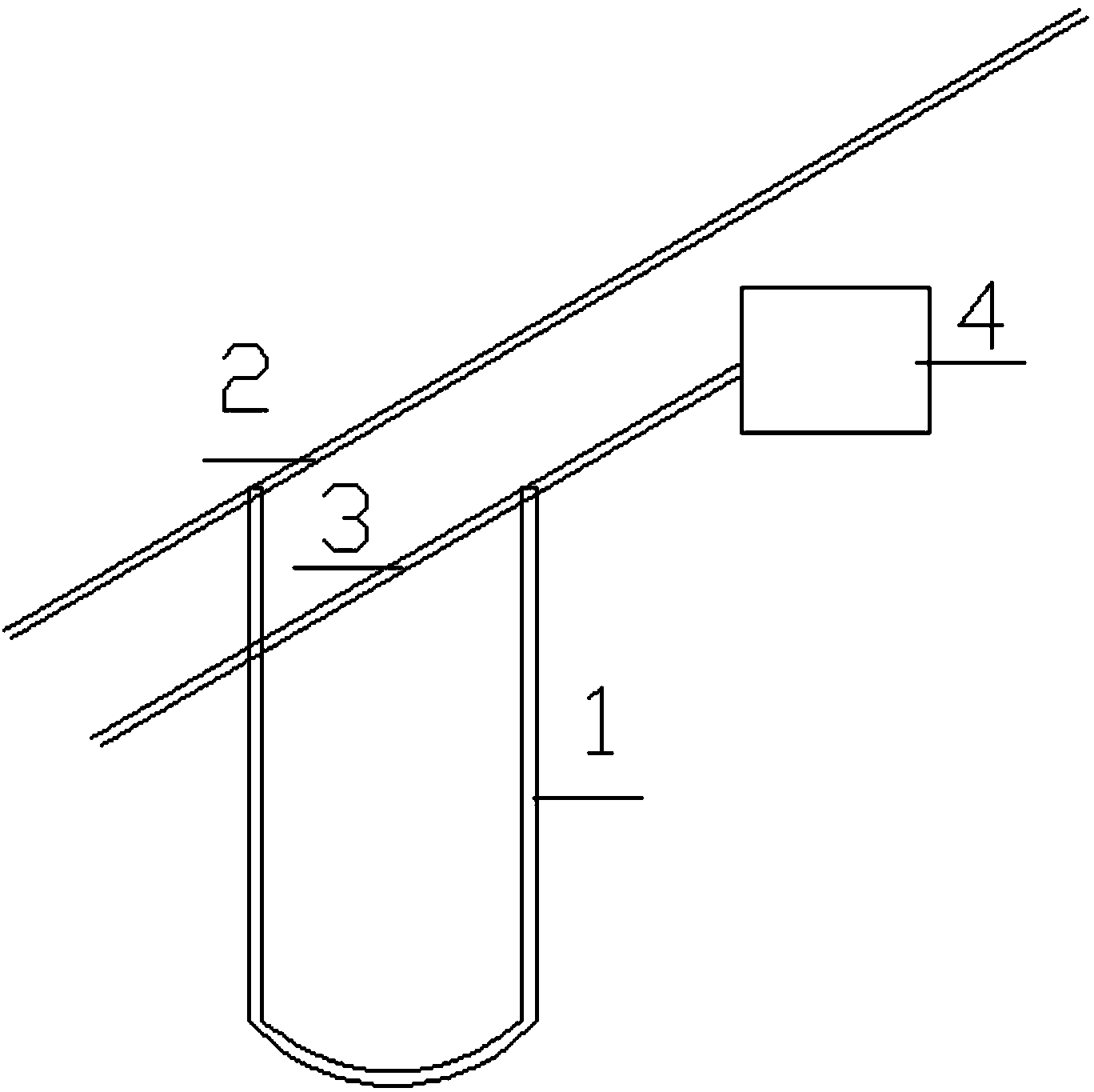
[0043] One end of the drainage board 1 is connected to a vacuum pipe network 2 , and the other end is connected to a vacuum pipe network 3 , and the connected vacuum pipe network 3 is connected to an air heating device 4 .
[0044] In this embodiment, the volume of the drying pool is 10m 3 , the specific steps are as follows:
[0045] (1) Pre-treatment: transport the sludge or sludge to be treated to the drying tank for preliminary precipitation;
[0046] (2) Setting of drainage boards: Insert several drainage boards in the silt or sludge obtained in step (1). A drainage channel is formed between the water-permeable layer and the drainage groove; the end of the drainage groove has a through first port and a second port; when the drainage board is inserted, the drainage groove is located in the silt or sludge, and the end of the drainage groove The first port and the second port protrude from the sludge or the surface of the sludge; and the first port or / and the second port a...
PUM
 Abstract
Description
Claims
Application Information
 - R&D
- Intellectual Property
- Life Sciences
- Materials
- Tech Scout
- Unparalleled Data Quality
- Higher Quality Content
- 60% Fewer Hallucinations
Browse by: Latest US Patents, China's latest patents, Technical Efficacy Thesaurus, Application Domain, Technology Topic, Popular Technical Reports.
© 2025 PatSnap. All rights reserved.Legal|Privacy policy|Modern Slavery Act Transparency Statement|Sitemap|About US| Contact US: help@patsnap.com