Annular bale plucker

A cotton plucking machine and ring-shaped technology, which is applied in the field of ring-shaped cotton plucking machines, can solve problems such as poor water spray uniformity, difficult humidity control, unfavorable production, etc., and achieve the effects of large coverage, uniform humidification, and good dust removal effect

Inactive Publication Date: 2014-07-23
罗静
View PDF0 Cites 5 Cited by
  • Summary
  • Abstract
  • Description
  • Claims
  • Application Information

AI Technical Summary

Problems solved by technology

[0007] In this traditional plucking machine, the nozzle can spray water during the circular movement of the platform, and the water spray is used to moisten the cotton layer below to meet the needs of the subsequent carding process; the existing plucking machine They are all single-step water spraying, the uniformity of water spraying is poor, the humidity is difficult to control, and it is not conducive to production. Due to such problems, it is necessary to invent a ring-shaped plucking machine

Method used


Image

  • Annular bale plucker
  • Annular bale plucker
  • Annular bale plucker

Examples


Embodiment 1

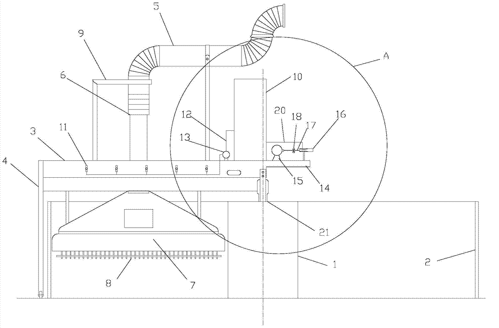
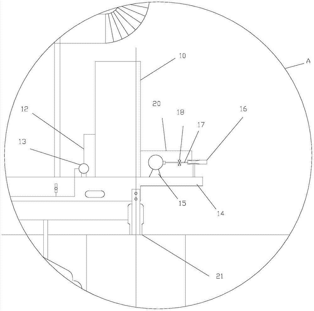
[0021] Such as figure 1 , 2 As shown, a ring-shaped cotton grabbing machine described in this embodiment includes an inner ring wall panel 1, an outer ring wall panel 2, a platform 3, a trolley 4, a cotton delivery tube 5, a telescopic tube 6, a cotton suction cover 7, a beater 8 and bracket 9, the inner ring wall panel 1 and the outer ring wall panel 2 are distributed concentrically; one end of the platform 3 is connected to the inner ring wall panel 1 through a slip ring mechanism 21, and the other end is connected to the top of the trolley 4, and the trolley 4 Located on the outer side of the outer wall panel 2, the telescopic tube 6 passes through the platform 3, the top of the telescopic tube 6 is connected to the cotton delivery tube 5, and the bottom is connected to the cotton suction cover 7, the beater 8 is located at the bottom of the cotton suction cover 7, and the bracket 9 is located on the platform 3 It is used to fix the telescopic tube 6, and the platform 3 is...

Embodiment 2

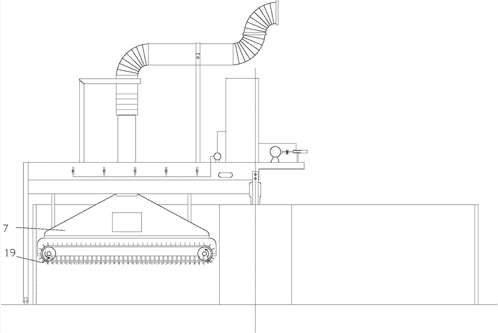
[0026] Such as image 3 As shown, the ring-shaped cotton grabbing machine described in this embodiment is different from Embodiment 1 in that: the rear side wall of the cotton suction cover 7 is provided with an electric conveyor belt 19 . Motorized conveyor belts 19 are used in the initial stages of production.

[0027] When feeding, the operator generally puts the cotton block near the outer ring wall panel 2. On the one hand, because the operator’s hand is not long enough, on the other hand, for the sake of labor saving, when the cotton plucker is just running, the cotton The layer is usually very full and forms a shape that is high on the outside and low on the inside. When the plucking machine rotates, the cotton layer overflows the outer ring wallboard 2 easily. In the production process, the cotton layer has a process of moving to the inner side, which can prevent the cotton layer from overflowing the outer ring wallboard 2, and when the cotton layer height is low, the...


PUM


Abstract

The invention discloses an annular bale plucker which comprises an inner ring wall board, an outer ring wall board, a platform, a trolley, a cotton conveying tube, a telescopic tube, a cotton sucking cover, a beater and a support. A reversed extended section is arranged on one side, opposite to the trolley of the platform, an air pump and an atomizing nozzle which can spray mist outwards are arranged on the reversed extended section, a water tank is further connected with a water inlet of the atomizing nozzle through a second water pipe, the air pump is connected with an air inlet of the atomizing nozzle through an air pipe, and an air valve is arranged on the air pipe. According to the bale plucker, the nozzle can spray mist outwards to achieve the main functions of humidification and dust removal. The atomizing nozzle can spray mist outwards 180 degrees away from the nozzle to cover the area between the inner ring wall board and the outer ring wall board, and finally the mist can fall on cotton layers between the inner ring wall board and the outer ring wall board. Mist humidification is fine and even and can be complementary with an existing nozzle to enable the cotton layers to be humidified evenly. On the other hand, the annular bale plucker can prevent cotton fibers from flying to guarantee physical health of operators.

Description

[0001] technical field [0002] The invention relates to a cotton plucking machine, in particular to an annular cotton plucking machine. [0003] Background technique [0004] Although the chemical fiber industry is becoming more and more developed and there are more and more varieties, cotton, as the main textile raw material, still plays an irreplaceable role. [0005] Cotton plucking machine is an important equipment in cotton processing, and its function is to disperse, grab and transport raw cotton pieces. [0006] The structure of the traditional plucking machine is like this: including the inner wall panel, the outer wall panel, the platform, the trolley, the cotton feeding pipe, the telescopic tube, the cotton suction cover, the beater and the bracket, the inner wall panel and the outer wall The plates are distributed in concentric circles; one end of the platform is connected to the inner ring wall plate through a slip ring mechanism, and the other end is connecte...

Claims


Application Information

Patent Timeline
Patent Type & Authority Applications(China)
IPC IPC(8): D01G7/06
Inventor 罗静
Owner 罗静
Why Eureka
Try Eureka