Freezing pipe injected grout non-return device

A technology of non-return devices and freezing pipes, which is applied in infrastructure engineering, soil protection, construction, etc., and can solve problems such as high construction costs, loss of shallow water resources, and low construction efficiency

Inactive Publication Date: 2014-07-23
BEIFANG YANSHENG ENG TECH
View PDF6 Cites 5 Cited by
  • Summary
  • Abstract
  • Description
  • Claims
  • Application Information

AI Technical Summary

Problems solved by technology

[0002] The freezing method is adopted in the construction of underground works, and the annular space between the frozen borehole and the frozen pipe forms a water conduction channel with hydraulic connection. Water and sand are easy to conduct to the deep part, resulting in the loss of water resources in the shallow part, so it is necessary to fix the pipe sealing water treatment for the frozen hole
At present, the water sealing treatment of the frozen hole solid pipe is divided into the early grouting solid pipe sealing water treatment and the later grouting solid pipe sealing water treatment. The drilling mud within the height range is replaced by cement slurry with a certain retarding time. Through the solidification of the cement slurry, the cementation between the frozen pipe and the formation is realized, and the water conduction channel is cut off. The performance of this kind of solid pipe sealing water treatment construction on the cement slurry There are strict requirements on the running time of frozen pipes, the process is complicated, the construction efficiency is low, and it is easy to cause the hole wall to collapse; the later stage grouting solid pipe sealing water treatment is more commonly used perforation, drilling and grouting technology, that is, in After the freezing construction is completed, the through hole of the frozen pipe is grouted to fill the annular space outside the frozen pipe, and the water sealing treatment of the solid pipe is completed. Whether it is perforating or drilling the frozen pipe, it is necessary to complete a very difficult and complicated operation. There are high requirements for construction technology and construction cost is relatively high

Method used


Image

  • Freezing pipe injected grout non-return device

Examples


Embodiment Construction

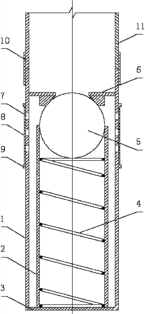
[0010] The present invention will be further described in conjunction with the accompanying drawings and implementation examples.

[0011] As shown in the accompanying drawings, this freezing pipe grouting check device has an outer pipe 1, and the outer pipe 1 adopts a pipe body with the same inner and outer diameters as the freezing pipe 11 used. An inner tube 2 is arranged inside the outer tube 1, and the inner tube 2 is placed at the center of the outer tube 1, and the length of the inner tube 2 is shorter than that of the outer tube 1. The lower ends of the outer tube 1 and the inner tube 2 are provided with a lower end sealing plate 3 that simultaneously forms the lower ends of the outer tube 1 and the inner tube 2 . During specific implementation, the lower end sealing plate 3 can also be set as a downwardly protruding conical plate, so as to facilitate the lowering of the tube. The inner tube 2 is provided with a spring 4 and a sphere 5 placed above the spring, the dia...


PUM


Abstract

The invention discloses a freezing pipe injected grout non-return device which is provided with an outer pipe and an inner pipe arranged in the outer pipe. A lower end sealing plate for simultaneously sealing the lower end of the outer pipe and the lower end of the inner pipe is arranged at the lower end of the outer pipe and the lower end of the inner pipe, a spring and a ball arranged on the spring are arranged in the inner pipe, an upper end sealing plate is arranged at the upper end of the outer pipe, a grout outlet matched with the ball is formed in the center of the upper end sealing plate, the outer pipe is provided with grout overflowing holes and a rubber sleeve for plugging the grout overflowing holes, and the upper end and the lower end of the rubber sleeve are provided with rubber sleeve fixing rings respectively. The freezing pipe injected grout non-return device is used for freezing hole pipe fixing water sealing processing, the construction technology of pipe fixing water sealing processing can be simplified, the requirements for construction devices and the construction technology can be reduced, the construction efficiency can be improved, the construction cost can be saved, and the construction quality can be guaranteed.

Description

technical field [0001] The invention relates to freezing construction equipment for underground engineering, in particular to a non-return device for freezing pipe grouting. Background technique [0002] The freezing method is adopted in the construction of underground works, and the annular space between the frozen borehole and the frozen pipe forms a water conduction channel with hydraulic connection. Water and sand are easy to conduct to the deep part, resulting in the loss of shallow water resources, so it is necessary to seal the frozen hole with water. At present, the water sealing treatment of the frozen hole solid pipe is divided into the early grouting solid pipe sealing water treatment and the later grouting solid pipe sealing water treatment. The drilling mud within the height range is replaced by cement slurry with a certain retarding time. Through the solidification of the cement slurry, the cementation between the frozen pipe and the formation is realized, and...

Claims


Application Information

Patent Timeline
Patent Type & Authority Applications(China)
IPC IPC(8): E02D3/115
Inventor 齐有军李海平
Owner BEIFANG YANSHENG ENG TECH
Why Eureka
Try Eureka