Roller cone bit, tooling for installing roller cone bit retaining ring and installation method of retaining ring

A technology of roller cone bit and retaining ring, which is used in drill bits, drilling equipment, earthwork drilling and other directions, can solve the problems of reducing the force area of ​​the tooth palm shaft, affecting the service life of the drill bit, and large diameter of the locking steel ball, and achieves heat treatment. The effect is good, the processing effect is good, and the effect of increasing the bearing area

Active Publication Date: 2017-02-15
TIANJIN LILIN BIT
View PDF7 Cites 0 Cited by
  • Summary
  • Abstract
  • Description
  • Claims
  • Application Information

AI Technical Summary

Problems solved by technology

In the above structure, due to the difference between the palm shaft and the hole of the gear shaft, the traditional locking steel ball is used for locking. Since the locking steel ball needs to be installed on the tooth palm shaft, a locking steel ball groove needs to be opened and inserted into the plug. pin, it is also necessary to open a limit groove on the hole of the gear shaft to limit the movement of the locking steel ball, and the diameter of the locking steel ball is relatively large, which occupies the space of the tooth palm shaft, and the bearing capacity of the tooth palm shaft The force area is reduced, and the coexistence of large and small shafts is adopted. Due to the low force of the small bearing, it is often prone to breakage, which in turn affects the service life of the drill bit

Method used


Image

  • Roller cone bit, tooling for installing roller cone bit retaining ring and installation method of retaining ring
  • Roller cone bit, tooling for installing roller cone bit retaining ring and installation method of retaining ring
  • Roller cone bit, tooling for installing roller cone bit retaining ring and installation method of retaining ring

Examples


Embodiment Construction

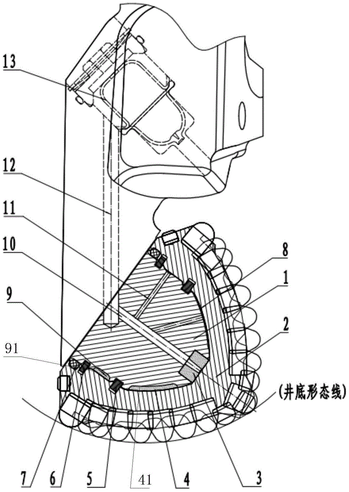
[0022] The specific implementation manner of the present invention will be described in detail below in conjunction with the accompanying drawings and preferred embodiments. As shown in the figure: a roller cone bit, including cone shaft hole 2, tooth palm shaft 1, sealing system 7, oil storage compensation pressure balance system 13, the cone shaft hole is sleeved on the tooth palm shaft, and the sealing system is set Seal the two between the cone shaft hole and the tooth palm shaft, the oil storage compensation pressure balance system communicates with the bearing center oil hole 10 on the tooth palm shaft through the long oil hole 12, the convex arc surface of the cone shaft hole The radian of the convex arc surface is the same as the shape of the bottom of the well and parallel to the bottom of the well. By adding the main bearing surface of the bearing shaft, the unstable phenomenon caused by the local force of the bearing shaft is prevented, and the stability of the dril...


PUM


Abstract

The invention relates to the technical field of drilling tools, in particular to a roller bit. The roller bit comprises a roller shaft hole, a roller palm shaft, a sealing system and an oil storing and compensating and pressure balancing system, wherein a first limiting groove is formed in the circumference of the roller palm shaft, a second limiting groove is formed in the roller shaft hole corresponding to the first limiting groove, and cross section check rings are installed in the first limiting groove and the second limiting groove; the roller palm shaft is composed of a large shaft of a bearing and an inclined shaft, the stressed face, parallel with the shaft bottom, of the bottom of the inclined shaft is provided with a first hard alloy layer, and a long oil groove is formed in the back side of the stressed face of the inclined shaft. A strong cross section check ring bearing locking system replaces a steel ball locking system, valuable bearing space is saved, the stressed area of the bearing is increased, the bearing structure is simplified, the oil membrane area of lubricating oil is increased when the stressed area of the sliding bearing is increased, and the roller bit can better adapt to orientated drilling under a high drilling-pressure and high-temperature environment.

Description

technical field [0001] The invention relates to the technical field of drilling tools, in particular to a roller cone bit. Background technique [0002] The roller cone bit is a tool for breaking rocks in the earth's crust, and is widely used in oil, natural gas drilling, and other mineral resource drilling and development. [0003] The working load of the roller cone bit is very heavy, the transmission force reaches hundreds of kilonewtons, and the transmission mechanical power reaches tens of kilowatts. The working environment is harsh. It is a high-pressure and high-temperature drilling fluid containing sand particles and corrosive substances, and the narrow borehole limits the volume of the drill bit, which ultimately limits the force-bearing area of ​​the sliding bearing. Therefore, the cone bearing is extremely small under severe working conditions. The force-bearing area must bear a lot of drilling pressure and torque. With the development of drilling technology to ...

Claims


Application Information

Patent Timeline
Patent Type & Authority Patents(China)
IPC IPC(8): E21B10/52E21B10/22E21B10/24B25B27/02
Inventor 陈斌
Owner TIANJIN LILIN BIT
Why Eureka
Try Eureka