Cylindrical cyclone separation device and special cyclone guide ring for same

A technology of swirl separation device and guide ring, which is applied in the direction of combination device, noise reduction device, exhaust device, etc., can solve the problems of automobile engine damage, insufficient utilization rate, and insufficient reduction of carbon deposition, so as to achieve adsorption of harmful gases, The effect of reducing vehicle emissions and saving fuel consumption

Inactive Publication Date: 2014-07-23
周伟波
View PDF5 Cites 5 Cited by
  • Summary
  • Abstract
  • Description
  • Claims
  • Application Information

AI Technical Summary

Problems solved by technology

At present, various fuel-saving technologies in the automotive industry emerge in endlessly. In terms of improving fuel efficiency, measures such as electronic fuel control and brake fuel control are mainly used. Combustion, some unburned fuel is still discharged through the engine as exhaust gas, its utilization rate is not high enough, there is still room for improvement, it is not good enough in reducing carbon deposition, and it is easy to cause damage to the car engine
The intake air of the existing automobile engine enters the engine through the intake throttle, wherein part of the exhaust gas after the combustion of the engine is discharged from the exhaust pipe, and the other part of the exhaust gas is directly sent into the intake throttle by the exhaust pipe and then enters the engine for combustion. Because the exhaust gas contains engine oil and other substances harmful to the engine, the combustion efficiency of the engine is reduced, and carbon deposits are easy to occur, which affects the efficiency and service life of the engine

Method used


Image

  • Cylindrical cyclone separation device and special cyclone guide ring for same
  • Cylindrical cyclone separation device and special cyclone guide ring for same
  • Cylindrical cyclone separation device and special cyclone guide ring for same

Examples


Embodiment 1

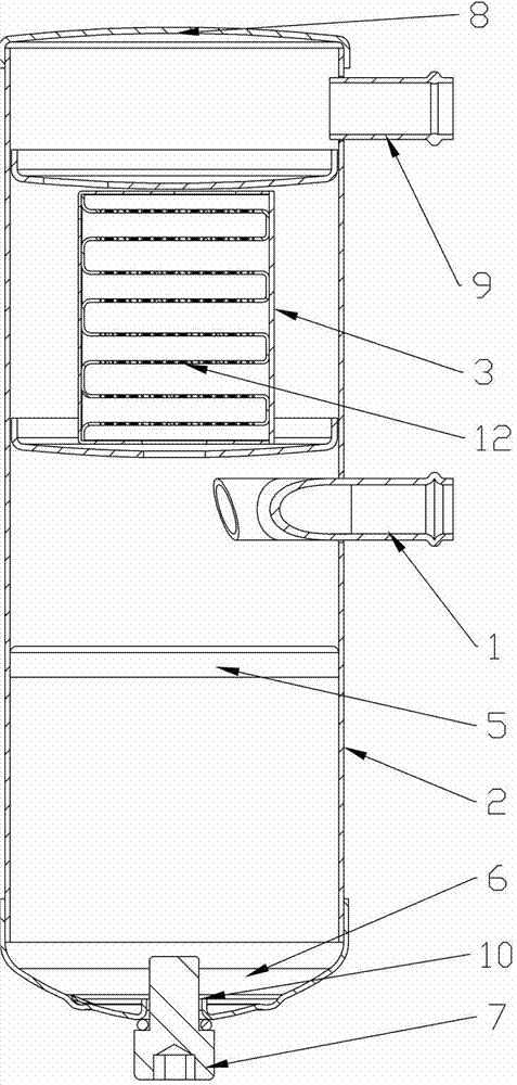
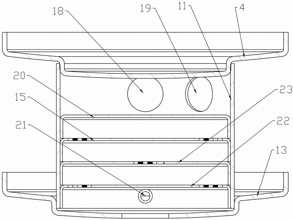
[0017] Embodiment 1, the present invention includes a cylinder 2, an air inlet pipe 1 and an outlet pipe joint 9, and is characterized in that: both ends of the cylinder 2 are sealed, and a swirl guide ring 5 is arranged in the middle and lower part of the cylinder 2 in a sealed fit. The cylinder body 2 on the upper part of the swirl guide ring 5 is provided with an air intake through hole and is sealed and fitted with the air intake pipe 1. The upper part of the air intake pipe 1 in the cylinder body 2 is provided with a lower partition 13 which is sealed and fitted with the cylinder body 2. The plate 13 divides the cylinder 2 into an upper filter chamber and a lower cyclone separation chamber. The upper part of the lower partition 13 is sealed with a filter element 3, and the lower partition 13 communicates with the cyclone chamber. The upper end of the filter element 3 is provided with a 2 The sealed upper partition 4, the upper and lower ends of the filter element 3 are res...

Embodiment 2

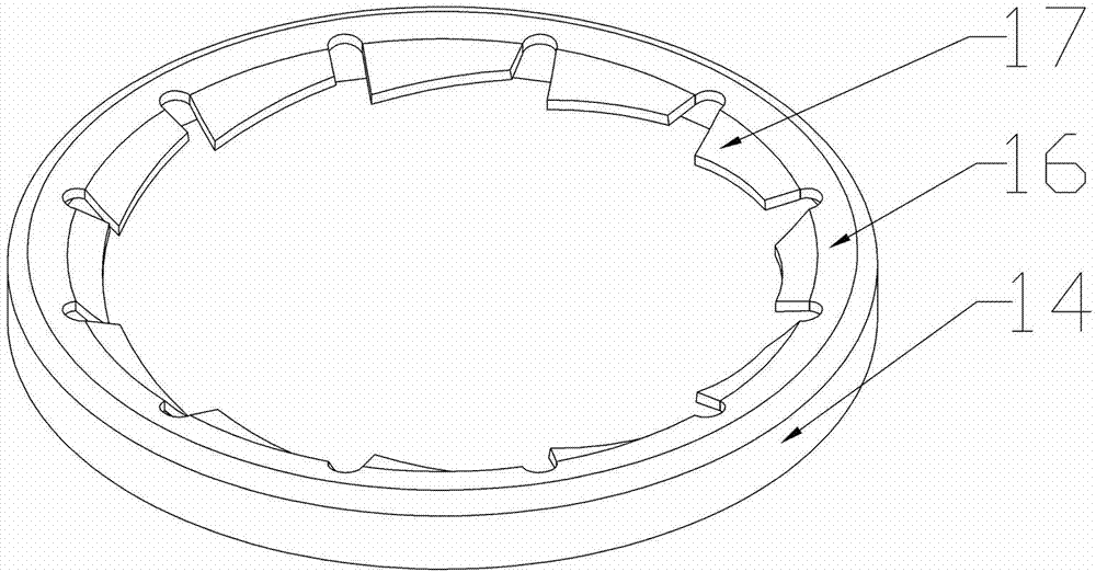
[0018] Embodiment 2, the swirl guide ring 5 of the present invention includes a ring wall 14, a blade ring 16, and a swirl guide vane 17, the blade ring 16 is arranged on the ring wall 14, and the outer diameter of the ring wall 14 is slightly larger than the inner diameter of the cylinder 2, The swirl guide ring 5 can be stuck in the cylinder body 2, and the swirl guide vanes 17 are arranged on the vane ring 16, and the surface is mirror-polished to reduce resistance. refer to Figure 1 to Figure 3 , all the other are with embodiment 1.

Embodiment 3

[0019] Embodiment 3, the vane circle 16 of the present invention is slightly inclined inward, the edge of the vane circle 16 is arc-shaped, and the vane circle 16 is provided with 3 or more swirl flow guide vanes 17, between which swirl flow guide vanes 17 The swirl guide vane 17 is inclined inwardly, the edge of the swirl guide vane 17 is high and low, the swirl guide vane 17 is set to be high on the left and low on the right, and the swirl guide vane circle 17 is in a counterclockwise direction as a whole. The air intake direction of the air pipe 1 matches, so that the gas enters and blows on the blades, which can strengthen the swirl velocity of the gas and guide the gas to form a rising swirl. refer to Figure 1 to Figure 3 , and the rest are the same as the above-mentioned embodiment.


PUM


Abstract

The invention provides a cylindrical cyclone separation device and a special cyclone guide ring for the same, and belongs to an energy-saving emission-reducing device. The cylindrical cyclone separation device and the special cyclone guide ring for the cylindrical cyclone separation device mainly solve the technical problems that an existing fuel engine is not high in use efficiency and more in exhausted waste gas, pollutes environment and the like. According to the technical scheme, the cylindrical cyclone separation device is characterized in that the two ends of a cylinder body (2) are sealed, the cyclone guide ring (5) is arranged on the lower middle portion of the cylinder body (2), the position, located on the upper portion of the cyclone guide ring (5), of the cylinder body (2) is provided with an air suction through hole, an air inlet pipe (1) is installed in the air suction through hole, a lower partition plate (13) is arranged at the position, located on the upper portion of the air inlet pipe (1), in the cylinder body (2), a filter element (3) is arranged on the upper portion of the lower partition plate (13), the lower partition plate (13) is communicated with a cyclone cavity, an upper partition plate (4) is arranged at the upper end of the filter element (3), the upper partition plate (4) is communicated with the filter cavity, and the outer wall of the upper portion of the cylinder body (2) is provided with an exhaust through hole, and an air outlet pipe connector (9) is installed in the exhaust through hole in a matched mode. The cylindrical cyclone separation device and the special cyclone guide ring are mainly used for energy conservation and emission reduction of fuel engines.

Description

technical field [0001] The invention relates to a cyclone separation device, in particular to a cylindrical cyclone separation device and a special swirl guide ring thereof. Background technique [0002] At present, cars have been owned by more and more consumers, and they have evolved from luxury goods to ordinary means of transportation. How to reduce fuel consumption, save energy, and at the same time reduce vehicle exhaust emissions and protect engines has become a common concern of all sectors of society. At present, various fuel-saving technologies in the automotive industry emerge in endlessly. In terms of improving fuel efficiency, measures such as electronic fuel control and brake fuel control are mainly used. Combustion, some unburned fuel is still discharged through the engine as exhaust gas, its utilization rate is not high enough, there is still room for improvement, it is not good enough in reducing carbon deposition, and it is easy to cause damage to the car ...

Claims


Application Information

Patent Timeline
Patent Type & Authority Applications(China)
IPC IPC(8): F01N3/00B01D50/00B01D53/24
Inventor 周伟波周胤
Owner 周伟波
Why Eureka
Try Eureka