

Compound type hydraulic drive device
A type of transmission and composite technology, applied in transmission boxes, transmission devices, fluid transmission devices, etc., can solve the problems of low efficiency, small speed change range, low power, etc., and achieve easy maintenance, convenient control, and reduced emissions. Effect
- Summary
- Abstract
- Description
- Claims
- Application Information
AI Technical Summary
Problems solved by technology
Method used
Image

Examples
Embodiment 1
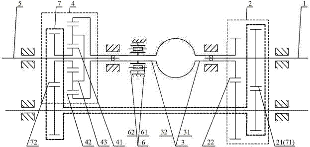
[0058] Such as figure 1 As shown in , a composite hydraulic transmission includes an input shaft 1, a speed change unit 2, a hydraulic transmission 3, a speed-combining unit 4, an output shaft 5, and a controller 6. The input shaft 1 and the output A transmission unit 2, a hydraulic transmission 3, a speed transfer unit 4, and a controller 6 are arranged between the shafts 5. The transmission unit 2 includes an input end 21 and an output end 22. The speed transfer unit 4 includes a first The input end 41, the second input end 42, the output end 43, the input end 21 of the speed change unit 2 and the first input end 41 of the speed transfer unit 4 are respectively connected with the input shaft 1, and the output end 22 of the speed change unit 2 is connected with the hydraulic transmission The input end 31 of the actuator 3 is connected, the output end 32 of the hydraulic actuator 3 and the input end 61 of the controller 6 are respectively connected with the second input end 42...
Embodiment 2
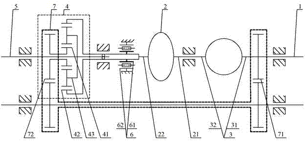
[0072] Such as figure 2 As shown in , a composite hydraulic transmission includes an input shaft 1, a speed change unit 2, a hydraulic transmission 3, a speed-combining unit 4, and an output shaft 5. Between the input shaft 1 and the output shaft 5 A speed change unit 2, a hydraulic transmission 3, and a speed transfer unit 4 are provided, the speed change unit 2 includes an input end 21, an output end 22, and the speed transfer unit 4 includes a first input end 41, a second input end 42. The output end 43, the input end 21 of the speed change unit 2 and the first input end 41 of the speed transfer unit 4 are respectively connected to the input shaft 1, the output end 22 of the speed change unit 2 is connected to the input end 31 of the hydraulic transmission 3, The output end 32 of the hydraulic transmission 3 is connected to the second input end 42 of the speed-combining unit 4 , and the output end 43 of the speed-combining unit 4 is connected to the output shaft 5 .
[00...
Embodiment 3
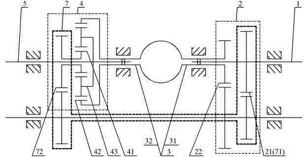
[0084] Such as image 3 As shown in , a composite hydraulic transmission includes an input shaft 1, a speed change unit 2, a hydraulic transmission 3, a speed-combining unit 4, an output shaft 5, and a controller 6. The input shaft 1 and the output A transmission unit 2, a hydraulic transmission 3, a speed transfer unit 4, and a controller 6 are arranged between the shafts 5. The transmission unit 2 includes an input end 21 and an output end 22. The speed transfer unit 4 includes a first The input end 41, the second input end 42, the output end 43, the input end 31 of the hydraulic actuator 3 and the first input end 41 of the speed converging unit 4 are respectively connected with the input shaft 1, and the output end 32 of the hydraulic actuator 3 It is connected with the input end 21 of the speed change unit 2, the output end 22 of the speed change unit 2 and the input end 61 of the controller 6 are respectively connected with the second input end 42 of the speed transfer un...
PUM
 Abstract
Description
Claims
Application Information