A low-swirl combustor head structure for low emission of aero-engine

A technology for aero-engines and combustion chambers, applied in the direction of combustion chambers, continuous combustion chambers, combustion methods, etc., can solve problems such as reduction, achieve the effects of reducing pollution emissions, reducing pollution emissions, ensuring stability and combustion efficiency

Active Publication Date: 2015-12-09
BEIHANG UNIV
View PDF5 Cites 1 Cited by
  • Summary
  • Abstract
  • Description
  • Claims
  • Application Information

AI Technical Summary

Problems solved by technology

[0007] The technical problem to be solved by the present invention is to overcome the deficiencies of the prior art, introduce the low-swirl combustion technology of gaseous fuel to the field of liquid fuel combustion, and provide a low-swirl aero-engine that can use liquid aviation kerosene as fuel The head structure of the low-pollution combustion chamber, the pre-combustion stage of the head structure adopts low-swirl combustion technology to create a flow expansion structure downstream of the combustion chamber, ensuring combustion stability under extremely lean combustion conditions, reducing the temperature and combustion of the combustion zone Product residence time, reduce nitrogen oxides NOx pollution emissions under various working conditions, and further significantly reduce the pollution emissions of aero-engines in the entire landing-take-off LTO cycle

Method used


Image

  • A low-swirl combustor head structure for low emission of aero-engine
  • A low-swirl combustor head structure for low emission of aero-engine
  • A low-swirl combustor head structure for low emission of aero-engine

Examples


Embodiment Construction

[0027] The present invention will be further described below in conjunction with the accompanying drawings and specific embodiments.

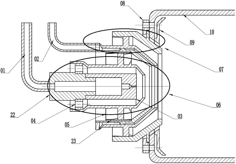
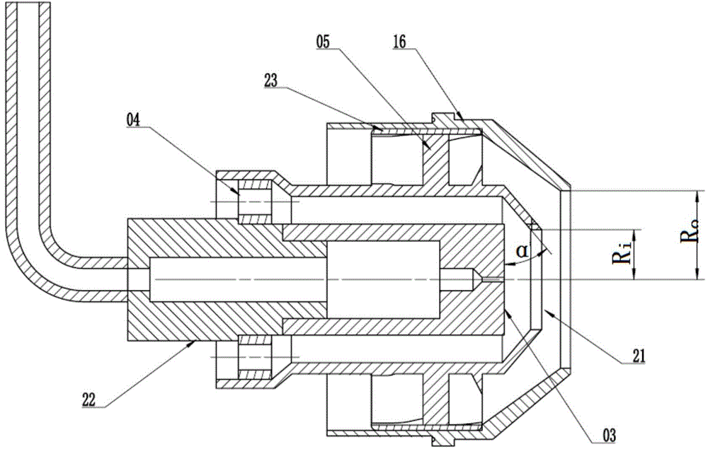
[0028] figure 1 It is a general cross-sectional view of the head structure of the combustion chamber of the present invention. The main combustion stage is fixed on the flame cylinder through the swirler mounting plate, and then the assembled pre-combustion stage is inserted into the main combustion stage in the axial direction. The ring is matched with the inner ring of the pre-film air atomizing nozzle, so that the main combustion stage and the pre-combustion stage are assembled together in a concentric manner, the pre-combustion stage is in the center, and the main combustion stage is arranged on the periphery of the pre-combustion stage. The double oil circuit nozzles are evenly arranged along the circumference of the entire engine, and the number is 12 to 30. figure 2 It is a sectional view of the pre-combustion stage structure of the pr...


PUM


Abstract

The invention provides a low-emission low-rotational-flow combustion chamber head structure for an airascraft engine. The low-emission low-rotational-flow combustion chamber head structure comprises a pre-burning level and a main-burning level. The pre-burning level is designed with low rotational flow, that is the gas flow is divided into two parts through an inner ring of a cyclone, one part of the flow forms jet flow with the extremely-low rotational flow strength through a current limiting plate of a center channel, and the other part of the flow forms rotational jet flow with the large rotational flow strength through an outer-side cyclone. Pre-burning level fuel is ejected from a centrifugal nozzle and then enters the combustion chamber along with pre-burning level jet flow. A pre-film type air atomizing nozzle is adopted in the main-burning level for supplying oil, the fuel is sheared and atomized by rotational jet flow, ejected by a pre-burning level external cyclone, of fuel and rotational gas flow, ejected by a main-burning level cyclone and then enters the combustion chamber. Due to a low-rotational-flow flow field, the staying time of combustion products is reduced, generation of heating power type NOx is reduced, and the combustion chamber can work stably in extremely-poor conditions. Working can be achieved by replacing the combustion chamber head of the aircraft engine, the requirement for transforming the engine is extremely low, the pollution emission level in the whole landing-taking off circulation can be reduced, and earnings are obvious.

Description

technical field [0001] The invention relates to the technical field of aviation gas turbines, in particular to a low-swirl combustor head structure for low emission of aviation engines. Background technique [0002] Combustion chambers of civil aero-engines must meet increasingly stringent aero-engine pollution emission standards. At present, the world's three major aero-engine manufacturers GE, PW and RR have already started research on low-pollution combustion chambers. In China, Beijing University of Aeronautics and Astronautics has also applied for a number of patents for low-pollution combustors of aviation gas turbines. Emissions have been reduced, but further reductions in pollution emissions have become increasingly difficult. [0003] At present, the NOx generation in the combustion chamber is still dominated by heat. Therefore, the core issue of reducing NOx emissions in low-pollution combustion chambers is to reduce the average temperature of the combustion zone ...

Claims


Application Information

Patent Timeline
Patent Type & Authority Patents(China)
IPC IPC(8): F23R3/58F23R3/38
Inventor 于博文张弛林宇震杨谦刘成川
Owner BEIHANG UNIV
Why Eureka
Try Eureka