Plate heat exchanger and fluid distributers and plates thereof

A fluid distributor, plate heat exchanger technology, applied in the direction of heat exchanger type, heat exchanger shell, indirect heat exchanger, etc., can solve the problem of reducing heat exchange performance of heat exchanger, reducing heat exchange performance, fluid flow distribution Non-uniformity and other problems, to achieve the effect of improving evaporation and vaporization efficiency, uniform fluid flow distribution, and improving plate utilization

Active Publication Date: 2014-07-23
ZHEJIANG FORWON PLATE HEAT EXCHANGER
View PDF6 Cites 17 Cited by
  • Summary
  • Abstract
  • Description
  • Claims
  • Application Information

AI Technical Summary

Problems solved by technology

[0003] First, most of the distributors of plate heat exchangers use linear injection technology. When high-pressure liquid refrigerant, especially gas-liquid two-phase mixed refrigerant, is sprayed from the distributor hole, it cannot achieve sufficient atomization, which affects the liquid refrigerant. Rapid volatilization, which increases the flow resistance and reduces the heat transfer performance of the heat exchanger
[0004] Second, in the flow channel composed of uniformly distributed corrugated plates, the flow distribution of the fluid is uneven. The flow velocity in the area near the straight line from the inlet to the outlet is relatively high. The farther away from this area, the smaller the flow velocity, and the flow distribution in the flow channel is uneven. Will lead to increased flow resistance and reduced heat transfer performance of the heat exchanger
[0005] Third, after the gas-liquid two-phase mixed refrigerant enters the distributor, it flows into the flow channel between the plates without sufficient pre-mixing, resulting in a large flow resistance, and the flow cannot be effectively and evenly distributed and flow uniformly in the flow channel between the plates, resulting in The pressure drop of the heat exchanger is large and the heat transfer performance is reduced

Method used


Image

  • Plate heat exchanger and fluid distributers and plates thereof
  • Plate heat exchanger and fluid distributers and plates thereof
  • Plate heat exchanger and fluid distributers and plates thereof

Examples


Embodiment 1

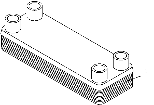
[0034] The specific structure and assembly relationship of the fluid distributor Figure 1 to Figure 6 Shown.

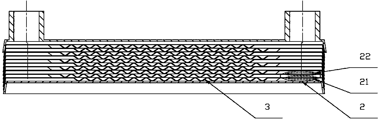
[0035] Such as figure 1 with figure 2 As shown, the plate heat exchanger is laminated with multiple layers of plates 1 with herringbone corrugations 3.

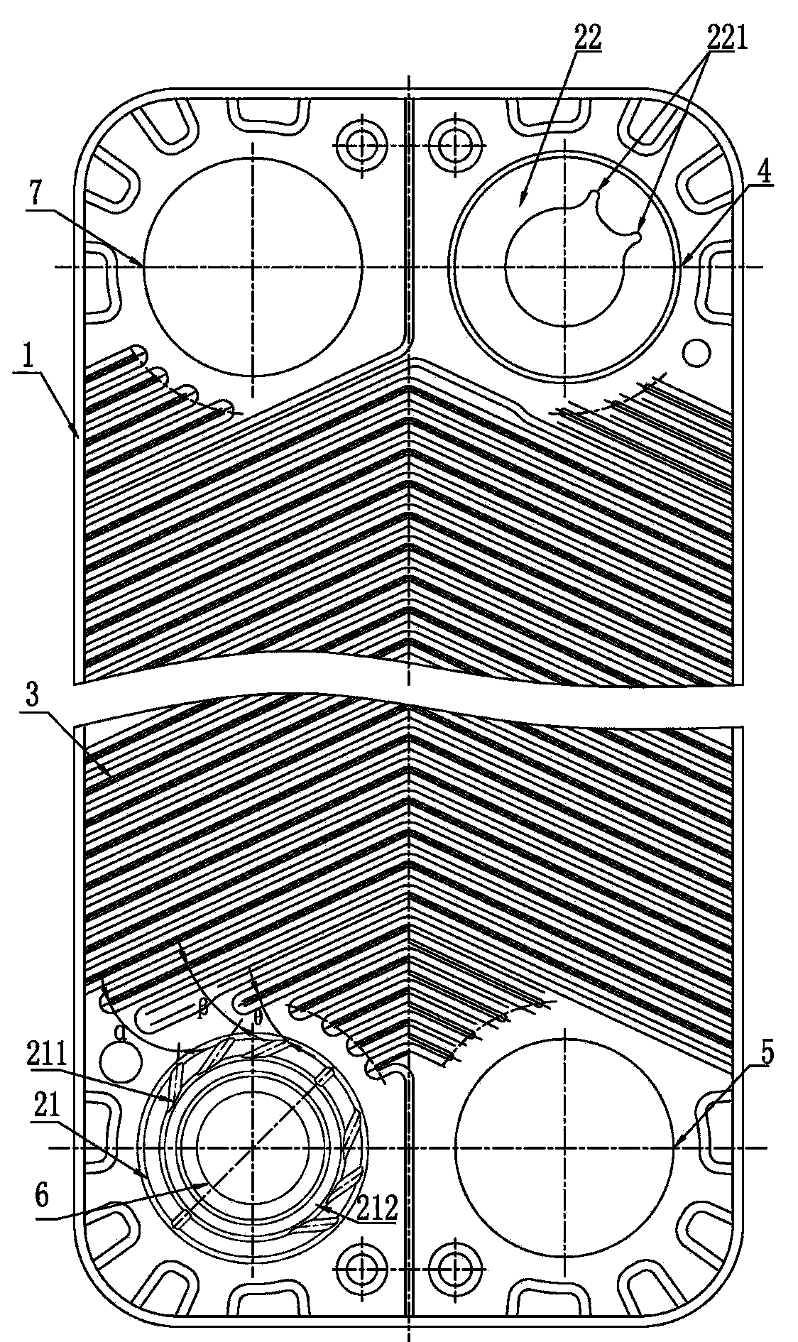
[0036] Such as figure 2 with image 3 As shown, the four corners of the illustrated plate 1 are provided with a corner hole. The second corner hole 7 and the fourth corner hole 5 are only used as fluid flow holes.

[0037] Such as Figure 1 to Figure 4 As shown, the plate 1 is also provided with a fluid distributor, the fluid distributor includes a plurality of stacked interlayer fluid distributors 2, and the interlayer fluid distributor 2 includes a first corner of the plate 1 The fluid distribution structure 21 on the side of the hole 6 and the fluid inlet structure 22 on the side wall of the third corner hole 4 of another plate 1 stacked adjacent thereto, the fluid distribution structure 21 and the fluid inlet struct...

Embodiment 2

[0040] In the specific implementation of the fluid distributor, the fluid distribution structure 21 includes an annular groove 212 arranged on the peripheral side of the first corner hole 6 and a plurality of fluid distribution holes 211 communicating with the outer side thereof. The fluid distribution holes 211 It also directly communicates with the concave portion of the herringbone wave 3 on the plate. The annular groove 212 allows the throttled gas-liquid two-phase fluid to be fully premixed. After the gas-liquid two-phase fluid is fully mixed in the annular groove 212, the fluid is dispersed into different herringbone corrugations through a plurality of fluid distribution holes 211. The recess.

[0041] The fluid distribution holes 211 are symmetrical about the bisector of the first and third quadrant angles and are distributed in a spiral centrifugal shape, which can force the fluid to start flowing along the corrugation of the plate on the other side away from the fluid di...

Embodiment 3

[0049] Combining the structure of the fluid distributor in Example 1 and Example 2, the present invention also constructs a plate for a plate heat exchanger. The plate is provided with the above-mentioned fluid distributor. The specific structure is as Figure 7 with Figure 8 As shown, the plate includes an A plate 8 and a V plate 9. The A corner hole 10 on the A plate 8 is provided with a fluid distribution structure 21 on the peripheral side, and the V plate corresponding to the position of the fluid distribution structure 21 on the A plate A fluid inlet structure 22 is provided on the side wall of the V-angle hole 11 of the plate.

[0050] In specific implementation, the multiple A plates 8 and V plates 9 are alternately stacked. At this time, the laminar flow distributor only forms an interlayer between the A corner hole of the A plate 8 and the V corner hole of the V plate 9 in the third quadrant. Fluid dispenser.

[0051] At the same time, because the cold and hot runners ar...


PUM


Abstract

The invention discloses a plate heat exchanger and fluid distributers of the plate heat exchanger. A plate heat exchanger comprises a plurality of plates in a stacked mode, wherein the plates are provided with a plurality of layers of herringbone corrugations, and the four corners of each plate are provided with corner holes. Each plate is provided with one fluid disturber. Each fluid distributer comprises a plurality of stacked inter-layer fluid distributers. Each inter-layer fluid distributer includes a fluid distribution structure and a fluid inlet structure, wherein each fluid distribution structure is arranged on the peripheral side of the corresponding first corner hole of the corresponding plate; each fluid inlet structure is arranged on the side wall of the corresponding third corner hole of one corresponding stacked and adjacent plate; the fluid distribution structures and the fluid inlet structures are coaxially and vertically matched, and at least one inter-layer fluid distributer is formed between any two adjacent plates. The fluid distributers can effectively lower fluid resistance, so that uniform atomization is performed on high-pressure fluid, and flow distribution of fluid in inter-plate flow channels is more uniform. In this way, the utilization rate of the plates is increased, and the heat exchange efficiency of the heat exchanger is effectively improved.

Description

Technical field [0001] The invention relates to the technical field of heat exchangers, in particular to a plate heat exchanger and its fluid distributor and plates. Background technique [0002] Plate heat exchangers are widely used in air conditioning, heating, food, chemical, power and machinery industries with their superior heat exchange performance. Ordinary plate plate heat exchangers can exert their advantages in single-phase heat exchange conditions, but in two-phase heat exchange conditions, such as when used as an evaporator, due to the difference in physical properties and flow patterns of gas-liquid two-phase fluids Larger, it is difficult to achieve uniform fluid distribution and uniform flow in the flow channel between the plates. The patent numbers are CN201163159Y, CN103348210A, CN103148727A and other inventions, which are effectively improved on the basis of ordinary plate heat exchangers. Some focus on the uniform distribution of two-phase fluid, and some focu...

Claims


Application Information

Patent Timeline
Patent Type & Authority Applications(China)
IPC IPC(8): F28D9/00F28F9/22F28F3/02
Inventor 马成稳林开兵
Owner ZHEJIANG FORWON PLATE HEAT EXCHANGER
Why Eureka
Try Eureka