A valve electric device life test bench

A technology for valve electric and life testing, which is applied in the direction of measuring devices, testing of mechanical components, testing of machine/structural components, etc. It can solve problems such as failure to meet test procedures, high labor intensity, safety accidents, etc., and achieve simple and intuitive operation , real-time modification and monitoring, and the effect of increased automation

Inactive Publication Date: 2017-01-11
杨卫中
View PDF6 Cites 0 Cited by
  • Summary
  • Abstract
  • Description
  • Claims
  • Application Information

AI Technical Summary

Problems solved by technology

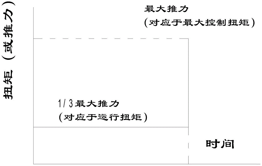
In this way, the control valve test cannot accurately simulate the real working conditions of the valve.
[0004] It turns out that the valve electric device life test bench of general enterprises uses disc springs to simulate the valve load. There are many shortcomings in the life test process, which cannot meet the requirements of the test regulations.
[0005] The electrical control adopts contactors, relays to control discrete components and simple disc spring control devices, which cannot carry out real-time data collection, analysis and communication of the valve electric device test. The torque is measured indirectly, that is, the maximum torque is determined through the torque protection on the valve electric device It is impossible to read the real-time torque during operation, so a long debugging and calibration process is required before the start of each test, which reduces the accuracy of the valve electric device life test and is difficult to meet user requirements
[0006] The life test needs to be done about 10,000 times. In order to shorten the test time, the valve electric device is generally used to work continuously. In this way, the valve electric device motor of the short-time working system will cause increased heat generation. Generally, the test bench does not have a circulating cooling system, and the life test can only use Artificial cooling is labor-intensive and prone to safety accidents

Method used


Image

  • A valve electric device life test bench
  • A valve electric device life test bench
  • A valve electric device life test bench

Examples


Embodiment Construction

[0035] The present invention is described in further detail now in conjunction with accompanying drawing. These drawings are all simplified schematic diagrams, which only illustrate the basic structure of the present invention in a schematic manner, so they only show the configurations related to the present invention.

[0036] Such as Figure 4 Figure 5 Figure 6 As shown, a valve electric device life test bench includes a workbench 1, a valve electric device 2 to be tested, a hydraulic control device 3 for providing loading torque to the valve electric device 2 to be tested, and an electric control console 4. The operating table 4 is respectively connected with the valve electric device 2, the hydraulic control device 3 and the working table 1.

[0037] The hydraulic control device 3 includes a fuel tank 31, a three-position four-way reversing valve 32 and an oil cylinder 33. The three-position four-way electromagnetic reversing valve 32 has a first interface, a second ...


PUM


Abstract

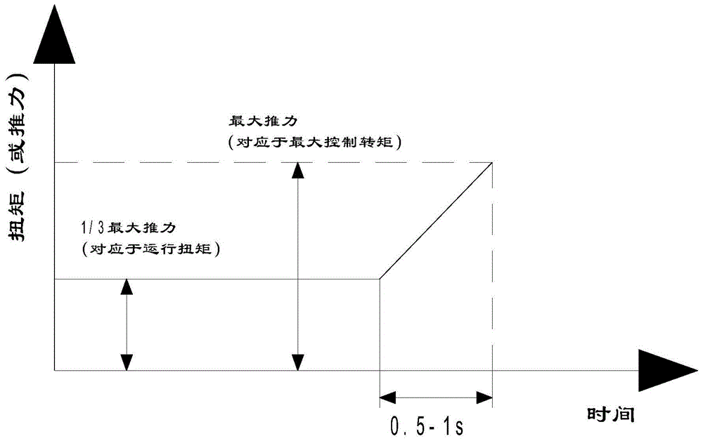
The invention relates to a service life test bed for a valve electric device. The service life test bed comprises a work table, the valve electric device to be tested, a hydraulic control device used for providing loading torque for the valve electric device to be tested, and an electric control operation platform. The electric control operation platform is in circuit connection with the valve electric device, the hydraulic control device and the work table. When the valve electric device to be tested bears the torque applied by a piston and is tested, a linear proportion relation exists between the torque output by the valve electric device and the work time. Through the loading torque provided for the valve electric device by the hydraulic control device, more real valve operation states can be simulated for the valve electric device, the efficiency of testing the valve electric device is improved, the testing process becomes simpler, the testing parameters are dynamically displayed, the accuracy can be guaranteed, and the automation degree is improved.

Description

technical field [0001] The invention relates to a service life test bench for a valve electric device. Background technique [0002] The valve electric device is an indispensable driving device to realize valve program control, automatic control and remote control. The life test detection method used by ordinary valve electric device manufacturers is generally low in efficiency and complicated in the test process. The test parameters cannot be dynamically presented, and the accuracy cannot be guaranteed. Personnel are on duty day and night. [0003] According to the actual operating requirements of the valve, the load characteristics are as follows: figure 1 As shown, during the life test of the valve electric device, it operates at the operating torque and closes at the maximum control torque (ie Figure 1 indicated by the vertical line). In this way, the control valve test cannot accurately simulate the real working conditions of the valve. [0004] It turns out that ...

Claims


Application Information

Patent Timeline
Patent Type & Authority Patents(China)
IPC IPC(8): G01M13/00
CPCG01M13/00
Inventor 杨卫中杨晓俊张伟峰张晓燕邵杰
Owner 杨卫中
Why Eureka
Try Eureka