Microslip testing platform for friction liner of elevator

A friction pad and test platform technology, applied in the direction of mechanical devices, measuring devices, instruments, etc., can solve the problems of single test parameters, single parameters, and frequent occurrence of slight slippage, and achieve various test parameters and real-time accurate measurement Effect

Inactive Publication Date: 2014-07-23
CHINA UNIV OF MINING & TECH
View PDF8 Cites 22 Cited by
  • Summary
  • Abstract
  • Description
  • Claims
  • Application Information

AI Technical Summary

Problems solved by technology

Patent application number 201010567284.4 discloses a "friction pad testing machine", which can accurately measure the friction force through a floating device, but the test parameters are relatively simple
The main problems existing in the existing steel wire rope and liner friction testing machine are: (1) Most testing machines use the plane method (two liners clamp the steel wire rope and then twitch the steel wire rope) to carry out the liner friction test, which is different from the actual working conditions. The arc-shaped gasket on the middle friction wheel does not match the friction of the steel wire rope; (2) The existing testing machine only performs one-way sliding test, and cannot perform reciprocating micro-sliding test. In actual working conditions, due to vibration and other reasons, the tension of the steel wire rope (3) The test parameters of the existing testing machine are relatively simple, and the change test of load, amplitude, frequency and friction arc cannot be realized

Method used


Image

  • Microslip testing platform for friction liner of elevator
  • Microslip testing platform for friction liner of elevator
  • Microslip testing platform for friction liner of elevator

Examples


Embodiment Construction

[0015] The present invention will be further explained below in conjunction with the accompanying drawings.

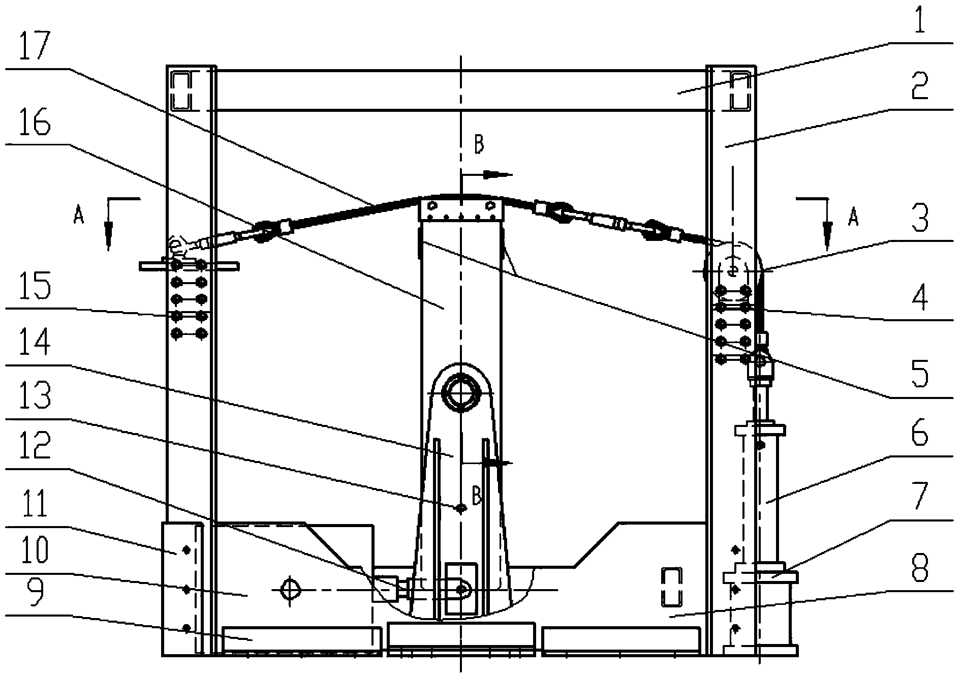
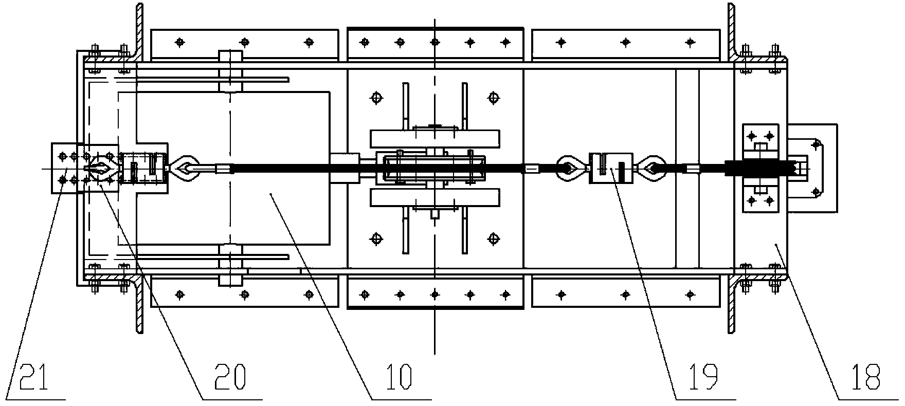
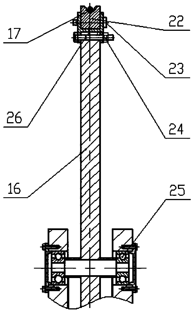
[0016] like Figures 1 to 3 As shown, the micro-slip test platform of the hoist friction lining of the present invention includes a support stand, a loading system, a power system and a measurement system.

[0017] The support platform includes a bottom beam 8, which is fixed by a fixed angle steel 9, and a support column 2 is welded at both ends of the bottom beam 8, and the top beam 1 is welded to the upper end of the support column 2, and a row of vertical columns is arranged on the support column 2 along the vertical direction. The fixing hole, the pulley bracket 18 and the adjustment bracket 2 are respectively fixed with the support column 2 by the first adjustment bolt 4 and the second adjustment bolt 15, and the pulley bracket 18 and the adjustment bracket can be adjusted respectively by the first adjustment bolt 4 and the second adjustment bolt 15 2 Position i...


PUM


Abstract

The invention relates to a microslip testing platform for a friction liner of an elevator. The microslip testing platform comprises a support rack, a loading system, a power system and a measurement system, wherein the support rack comprises a bottom beam; the two ends of the bottom beam are respectively provided with a support stand column; each support stand column is provided with a pulley bracket and an adjusting bracket; a fixed pulley is arranged on each pulley bracket; a fixed hook is arranged on each adjusting bracket; a bearing seat is arranged in the middle of the bottom beam; the middle part of a swing rod is articulated on the bearing seat by a bearing; the upper end of the swing rod is provided with a liner which is provided with an arc-shaped groove; the loading system comprises a steel wire rope set up on the arc-shaped groove of the liner; one end of the steel wire rope is connected with the fixed hooks, and the other end of the steel wire rope is connected with a piston rod of a hydraulic cylinder after winding the fixed pulleys; the power system comprises a vibration exciter; the vibration exciter is articulated with the lower end of the swing rod by a connecting rod; the measurement system comprises a tension sensor and a strain gauge. The microslip testing platform is capable of simulating the actual working conditions of the friction type elevator, and a microslip friction test with variable frequency, variable amplitude, variable load and variable radian can be realized.

Description

technical field [0001] The patent of the present invention relates to a friction lining micro-slip test platform for simulating the actual working conditions of a friction hoist, which can realize the friction slip of a small amplitude between the hoisting wire rope and the friction lining, and is used to study the hoisting wire rope and the friction lining The dynamic friction behavior between them and the tribological properties of friction lining materials and friction-enhancing greases. Background technique [0002] The multi-rope friction hoist is more and more used in the mine hoisting of deep and ultra-deep mines due to its large lifting capacity, large lifting height, high safety factor, low power consumption, small machine size, and low cost. middle. Friction lifting relies on the friction between the wire rope and the liner to transmit the force. The friction liner and the wire rope form a dual friction pair. The friction coefficient between the two directly affec...

Claims


Application Information

Patent Timeline
Patent Type & Authority Applications(China)
IPC IPC(8): G01N19/02
Inventor 张德坤郭永波王大刚
Owner CHINA UNIV OF MINING & TECH
Why Eureka
Try Eureka