Control method of multi-axis motion card control system

A control system and control method technology, applied in the direction of digital control, electrical program control, etc., can solve the problems of few motion control cassettes, non-motion control functions, inability to guarantee real-time multitasking, lack of flexibility in algorithm design, etc., to overcome Multi-thread resource sharing and mutual exclusion access conflicts, modular design, and reasonable scheduling effects

Inactive Publication Date: 2014-07-23
东莞市升力智能科技有限公司
View PDF2 Cites 26 Cited by
  • Summary
  • Abstract
  • Description
  • Claims
  • Application Information

AI Technical Summary

Benefits of technology

This technology allows for efficient use of resources across tasks or threads within an integrated computing environment with separate modules that work together based on their own scheduleings. It also includes techniques like round robin queuing methods used during execution time, effective handling of interference from shared memory, and utilizing FLASH RAM to distinguish and process various types of instructions efficiently without affecting any others' operations. Overall, this technology simplifies the overall architecture of these systems and enhances its performance capabilities.

Problems solved by technology

The technical problems addressed in this patent text are as follows: 1. The need for a motion controller with high computing performance, real-time performance, and stability for CNC systems. 2. The challenge of achieving parallel control logic for multi-axis linkage in a serially controlled DSP. 3. The limitation of FPGA in processing floating-point data. 4. The requirement to allocate software and hardware resources of DSP efficiently for various functions. 5. The need for a software structure that guarantees real-time requirements under multi-tasking and allows for easy software update and upgrade. 6. The limited availability of motion control cards with a small number of control axes and lack of non-motion control functions. 7. The low integration and lack of compatibility between non-motion control functions and motion control functions in existing motion control cards. 8. The need to improve the system scheduling and high-speed operation in motion control card implementations.

Method used


Image

  • Control method of multi-axis motion card control system
  • Control method of multi-axis motion card control system
  • Control method of multi-axis motion card control system

Examples


Embodiment

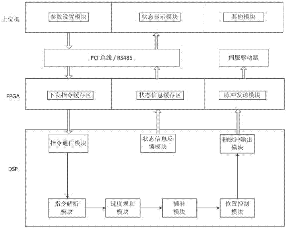
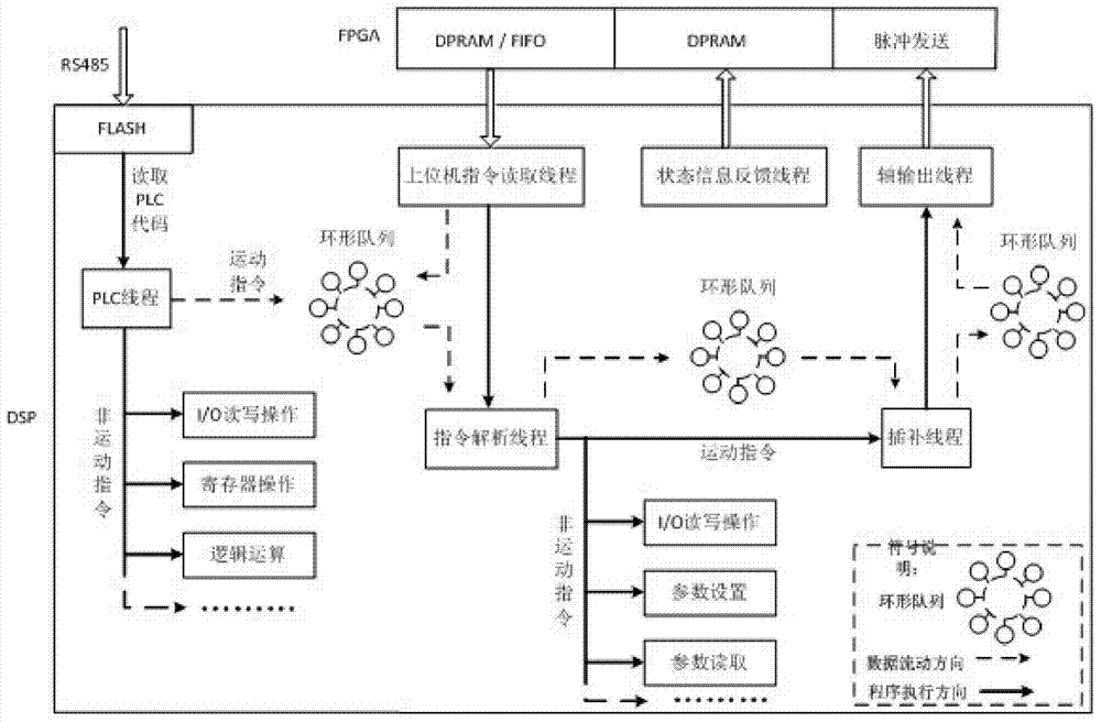
[0037] Such as figure 1 As shown, the 12-axis motion control card control system is divided into three parts: upper computer, motion control card and actuator. The user realizes system parameter setting and status information monitoring through the host computer interface; the FPGA internally realizes functions such as user command buffer, status information buffer, and output pulse transmission. There are two ways of communication between the host computer and FPGA: PCI bus and RS485 serial port; DSP It includes command communication module, command analysis module, speed planning module, interpolation module, position control module, axis pulse output module and status information feedback module. The underlying frame DSP of the 12-axis motion control card discussed in the present invention is connected to the FPGA through an EMIF (External Memory Interface, external memory interface) bus. attached figure 2 It is the underlying program architecture diagram of the 12-axis ...


PUM


Abstract

The invention discloses a control method of a multi-axis motion card control system, and relates to the technical field of mechanical automatic control. The method includes the following steps that a user sends instructions to a DSP in a motion control card through an upper computer; a instruction communication module in the DSP regularly scans an FIFO buffer region and a DPRAM buffer region in an FPGA; when reading the instructions, an instruction analysis module preferentially reads instructions in an emergency instruction circular queue, if emergency instructions need to be executed, the emergency instructions are firstly read, and if no instructions exist in an emergency instruction cache, instructions in an ordinary instruction circular queue are read; after the instructions are taken out from the circular queue, the instructions are analyzed; a speed planning module and an interpolation module calculate speed values of axes according to motion types and parameters. By the adoption of the method, operation efficiency of the system and data processing efficiency are improved, and high efficiency of operation of the system and data continuity are effectively guaranteed.

Description


Claims


Application Information

Patent Timeline
Owner 东莞市升力智能科技有限公司
Why Eureka
Try Eureka