System for intelligently monitoring factory environment quality

A technology of intelligent monitoring system and environmental quality, applied in the direction of comprehensive factory control, comprehensive factory control, transmission system, etc., can solve the problems of single monitoring person, inapplicable workshop workers, unable to monitor responsibility contract to individuals, etc., to achieve accurate collection of data. Effect

Inactive Publication Date: 2014-07-23
JIANGNAN UNIV
5 Cites 13 Cited by

AI-Extracted Technical Summary

Problems solved by technology

The existing monitors are too single, there is no hierarchical and role-based monitoring, and it is impossible to contract monitoring responsibilities to individuals
The existing...

Abstract

The invention relates to an intelligent monitoring system, in particular to a system for intelligently monitoring factory environment quality, and belongs to the technical field of factory environment monitoring. According to the technical scheme, the system for intelligently monitoring factory environment quality comprises a wireless data acquisition system connected with a controlled device and used for acquiring working environment information of the controlled device. The wireless data acquisition system transmits the acquired working environment information to a control center, and the control center processes the working environment information transmitted by the wireless data acquisition system and transmits the working environment information to a monitoring server, so that the monitored working environment information is transmitted to a remote control terminal through the monitoring server. The system is simple and compact in structure, wide in application range, safe and reliable, and capable of effectively monitoring factory environment quality.

Application Domain

Network topologiesTransmission +2

Technology Topic

EngineeringWorking environment +4

Image

  • System for intelligently monitoring factory environment quality
  • System for intelligently monitoring factory environment quality
  • System for intelligently monitoring factory environment quality

Examples

  • Experimental program(1)

Example Embodiment

[0020] The present invention will be further described below in conjunction with specific drawings and embodiments.
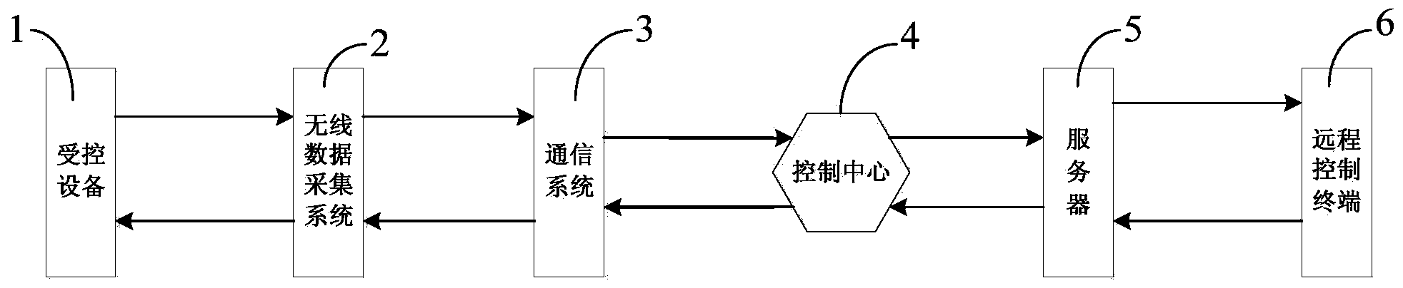
[0021] like figure 1 As shown: in order to effectively monitor the factory environment quality, the present invention includes a wireless data acquisition system 2 connected with the controlled equipment 1 and used to collect the working environment information of the controlled equipment 1, and the wireless data acquisition system 2 will collect The working environment information is transmitted to the control center 4, and the control center 4 processes the working environment information transmitted by the wireless data acquisition system 2 and transmits it to the monitoring server 5, so as to transmit the monitored working environment information to the remote control terminal through the monitoring server 5 6.
[0022] Specifically, the controlled device 1 is a working device located on a factory floor, and the state of the controlled device 1 can be effectively monitored by collecting the working environment of the controlled device 1 . The controlled equipment 1 collects data of working environment information through the wireless data collection system 2 and transmits the data to the control center 4 . Generally, there are multiple controlled devices 1 in the factory workshop, each controlled device 1 is equipped with a corresponding wireless data acquisition system 2, and the control center 4 is used for centralized management with all wireless data acquisition systems 2 in the factory. By transmitting the working environment information transmitted by the wireless data acquisition system 2 to the monitoring server 5, the remote control terminal 6 can check the working status of the controlled equipment 1 in time through the monitoring server 5, and realize effective monitoring of the factory environment quality.
[0023] Further, the monitoring server 5 can store the working environment information transmitted by the control center 4; the remote control terminal 6 can transmit working state adjustment instructions to the controlled equipment 1 through the monitoring server 5, the control center 4 and the wireless data acquisition system 2 , so as to adjust the working state of the controlled device 1 according to the monitored working environment information of the controlled device 1 . After the monitoring server 5 compactly stores the working environment information transmitted by the control center 4, the remote control terminal 6 communicates with the monitoring server 5 to obtain past environmental quality information of the controlled equipment 1. In the embodiment of the present invention, the environmental quality information reflects the working status of the controlled equipment 1, and the controlled equipment 1 may generally be a lathe or other processing equipment. In order to realize the feedback adjustment of the working state of the controlled device 1 according to the working environment information, the remote control terminal 6 can transmit the remote control command to the controlled device 1 through the monitoring server 5, the control center 4 and the wireless data acquisition system 2, and the controlled The device 1 can realize the state of continuing to work or waiting for work according to the remote control command, so as to ensure the working safety of the controlled device 1 .
[0024] The remote control terminal 6 includes a monitoring computer 11 and a mobile terminal 12, and the remote control terminal 6 is connected to the monitoring server 5 through the Internet. The mobile terminal 12 can be a smart phone or a tablet, etc., and the monitoring computer 11 is connected to the monitoring server 5 through a network.
[0025] like figure 2 , image 3 , Figure 4 and Figure 5 As shown, the wireless data collection system 2 includes an environment detection device for collecting the working environment information of the controlled equipment 1 and a collection terminal 7 for collecting the data of the environment detection device, and the collection terminal 7 communicates with the communication system 3 Control Center 4 wireless connection.
[0026] The first acquisition channel of the acquisition terminal 7 is connected to the environment detection device through a multiplexer 8, the second acquisition channel of the acquisition terminal 7 is connected to the vibration sensor 9, and the third acquisition channel of the acquisition terminal 7 is connected to the electric energy metering device 10 ; The environment detection device includes a noise sensor, a smoke sensor or a temperature and humidity sensor.
[0027] The multiplexer 8 encodes the detection data of the environmental detection device and transmits it to the collection terminal 7. The communication system 3 includes a Zigbee wireless network, and the collection terminal 7 transmits the coded detection data to the control center 4 through the Zigbee wireless network. Inside.
[0028] The acquisition terminal 7 increases or decreases the number of samples of the corresponding acquisition channel through an adaptive adjustment sampling method for the sampling numbers of the first acquisition channel, the second acquisition channel and the third acquisition channel.
[0029] The adaptive adjustment sampling method is as follows: setting the linear deviation average threshold value, and the acquisition terminal 7 calculates the sampling deviation average value of the first acquisition channel, the second acquisition channel, and the third acquisition channel; when the sampling deviation average value is greater than the linear deviation When the threshold is averaged, the acquisition terminal 7 increases the sampling number of the corresponding acquisition channel, otherwise, the acquisition terminal 7 decreases the sampling number of the corresponding acquisition channel.
[0030] Specifically, the wireless data collection system 2 is composed of several collection terminals 7 with built-in ZigBee transceiver modules and the same structure. Quality parameters, noise parameters, machine vibration parameters, electric energy metering devices, etc. In order to prevent too many ZigBee transceiver module signals in a certain space, signal interference or collision will affect the transmission effect, so a multiplexer 8 is configured for the acquisition terminal 7 . The acquisition terminal 7 can be composed of existing chips with Zigbee transceiver modules to realize the construction of a Zigbee network. Further, the chip in the acquisition terminal 7 can also implement some decoding and simple calculations. The specific functions can be set according to needs. I won't repeat them here.
[0031] The multiplexer 8 includes eight input ports and one output port, and the output ports of the sensors (except vibration sensors and electric energy metering devices) are respectively connected to the designated input ports of the multiplexer 8, and the output ports of the multiplexer 8 Connected to the first acquisition channel of the acquisition terminal 7, because the vibration sensor 9 and the electric energy metering device 10 are placed in special positions, the vibration sensor 9 and the electric energy metering device 10 are respectively connected to the second acquisition channel and the third acquisition channel of the acquisition terminal 7. aisle. Through the multiplexer 8, one acquisition terminal 7 can be connected with multiple sensors to complete multiple data transmissions. In order to facilitate the analysis of data sources, the data of the eight input ports of the multiplexer 8 and the three acquisition channels of the acquisition terminal 7 must be encoded. When the acquisition terminal 7 analyzes the data, the data must be decoded first.
[0032]When the multiplexer 8 started working, it first judged whether the eight channels had data transmission, and the channels without data transmission were closed. After the initial sampling number is completed, the collection work starts. The multiplexer 8 transmits the encoded data to the first collection channel of the collection terminal 7, and the sampling number of each channel is updated after the analysis of the collection terminal 7. The multiplexer 8 can adopt an existing structure, mainly realizing connection with multiple sensors, encoding the data of the sensors, and transmitting the encoded data to the acquisition terminal 7 .
[0033] When the collection terminal 7 is working, it first judges whether there is data in the three collection channels, and closes the channels without data. After the sampling numbers of the three channels are initialized, the sensor data per unit time is received, and the collected data is transmitted to the control center 4 through the communication system 3 on the one hand, which is convenient for the control center 4 to analyze the data; on the other hand, the collected data is decoded and The "adaptive adjustment sampling method" is used to analyze the data characteristics to obtain a new sampling number, and the updated sampling number is fed back to the corresponding sensor by the communication system.
[0034] Table 1 is the sensor distribution table of the workshop. The present invention configures different sensors for the collection terminal 7 according to the different attributes of the workshop.
[0035] Table 1 Workshop sensor distribution table
[0036] workshop type distributed sensor mold noise, vibration injection molding Air quality (various indicators), vibration, noise purify Air quality (multiple indicators), temperature and humidity, vibration assembly vibration storage smoke, noise Power distribution room Electric energy metering device, smoke
[0037] Generally, collecting data refers to collecting the same number of sensor data per unit time for each sensor, and then the processor program of the collecting terminal 7 enters an interrupt, and the interrupt first processes the data of a specific sensor according to the priority judgment. Although this method is simple, it completely ignores the characteristics of data changes, not only the average information of the collected data is less, but also causes a waste of bandwidth.
[0038] In the embodiment of the present invention, the adaptive adjustment sampling method is specifically:
[0039] random data P i Represents the i-th sampling value of data P, with n sampling values ​​P k-n+1 to P k , the sampling average of n sampling points is and where k=1,2,3..., n=1,2,3....
[0040] if the conditions are met Then define Pf t (m,n) is at the sampling point P t where the regression window width is m, and the sampling window width is n, the linear deviation mean ratio. Where t=1,2,3..., m=1,2,3..., n=1,2,3... and t-(n-1)>0.
[0041] It can be seen from the above that the average linear deviation ratio is usually a value greater than 0 and less than 1. In specific implementation, a linear deviation average threshold can be set according to the requirement of data accuracy. When the acquisition terminal 7 finishes one sampling, the sampling deviation average ratio is calculated, and compared with the linear deviation average threshold value, if the sampling deviation average value is greater than the linear deviation average threshold value, then the data fluctuation is relatively large and in a non-linear state, and sampling needs to be increased The number improves the sampling accuracy; otherwise, the number of samples is reduced to reduce the burden of data collection.
[0042] In the embodiment of the present invention, the communication system 3 generally refers to the communication link of the whole system, and the communication system 3 includes several routers. In the wireless data acquisition system 2, a Zigbee-based tree network structure connection is adopted between the acquisition terminal 7 and the routers. , the wireless data acquisition system 2 is connected to the control center 4 through the zigbee network. The control center 4 is essentially a coordinator, so it can be connected to the monitoring server 5 through a serial port. The monitoring server 5 uses the Internet network to facilitate the connection of remote control terminals . In particular, it should be pointed out that the data transmission of the communication system 3 is bidirectional. The communication link from the wireless data acquisition system 2 to the remote control terminal 6 mainly plays the role of transmitting sensor data to the remote control terminal 6, and from the remote control terminal 6 to the remote control terminal 6. The communication link of the wireless data acquisition system 2 mainly plays the role of sending user control instructions to the acquisition terminal. In the embodiment of the present invention, the control center 4 can be set according to the role and nature of the coordinator in the Zigbee network, and in specific implementation, the control center 4 can be implemented with a corresponding chip.
[0043] The control center 4 can manage the wireless data collection system 2 , upload and process the collected data, and transmit control instructions to the collection terminal 7 . After the control center 4 receives the data transmitted by the wireless data acquisition system 2, it analyzes and processes it. On the one hand, the analysis and processing capability of the control center 4 refers to converting the effective signal of the sensor into a symbol that users can understand according to the existing technology, such as performing frequency calculation on the noise signal, and converting the original voltage signal of the noise into a signal that meets the national standard. The sound pressure level signal, the unit is dB. Another aspect is to analyze the operation mode and state of the controlled object according to the sensor data. The analyzed and processed data is uploaded to the monitoring server 5 through the serial port.
[0044] The control center 4 can receive the instructions transmitted by the monitoring server 5, and the user can view the factory monitoring data and the status of the controlled equipment 1 on the remote control terminal 6, and issue control instructions. The remote control terminal 6 stores the received user control instructions in the monitoring server 5 , and then sends them to the control center 4 . The control center 4 determines the controlled device 1 of the control command, then encodes the received data, and then sends a control signal to the controlled device 1 through the wireless data acquisition system 2, such as Image 6 is the flow chart of the system.
[0045] Table 2 Sensor selection and controlled objects
[0046] sensor type Controlled object temperature air conditioner, machine humidity humidifier, dehumidifier noise Machine vibration Machine air quality doors and windows smoke Call the police Energy Metering Device Machine
[0047] In the embodiment of the present invention, the main function of the monitoring server 5 is to store the data and status of the controlled object transmitted from the control center 4 and the control instructions transmitted by the remote control terminal 6. The stored data can be used as historical data for the manager to analyze, and It is convenient for users to check in the future.
[0048] The remote control terminal 6 and the monitoring server 5 are connected through the Internet. Generally, the remote control terminal 6 is connected to the desktop computer through the Internet (i.e. wired Internet), so that the administrator can remotely view the data; but the monitoring of the controlled device 1 is in Completed in the workshop, workers have a large range of space activities in the workshop, and there is a one-to-many relationship between workers and controlled equipment 1, desktop computers are obviously not suitable for workers. In order to make it easier for the workers to implement management and monitoring, the remote control terminal 6 in the workshop should adopt a mobile terminal 12, such as a palm computer, a mobile phone, etc., and at this time, the monitoring server 5 and the remote control terminal 6 are connected through the mobile Internet (i.e. wireless Internet) .
[0049] The remote control terminal 6 can help the user to consult the historical data in the server, and the user can also send control instructions. On the remote monitoring terminal 6, users are divided into different roles, and different roles have respective permissions, and the permissions can only be changed by a system administrator or a higher-level role. When logging in, the user needs to enter the login account and password. In this way, it can prevent artificially changing the state of the controlled object and causing production loss, and it can be contracted to individuals according to the responsibility for the normal operation of the workshop production.
[0050] In summary, the present invention realizes real-time and accurate collection, remote transmission and humanized monitoring of factory environmental quality parameters, meets the requirements for real-time and dynamic monitoring of factory environmental quality, and realizes informatization, Transparent and networked management is of great significance to the monitoring of factory environmental quality.

PUM

no PUM

Description & Claims & Application Information

We can also present the details of the Description, Claims and Application information to help users get a comprehensive understanding of the technical details of the patent, such as background art, summary of invention, brief description of drawings, description of embodiments, and other original content. On the other hand, users can also determine the specific scope of protection of the technology through the list of claims; as well as understand the changes in the life cycle of the technology with the presentation of the patent timeline. Login to view more.

Similar technology patents

Odor collecting system and method

ActiveCN112570381Aaccurate collectionHigh control precision
Owner:HUNAN JUNXIN ENVIRONMENTAL PROTECTION CO LTD

Multi-modal information fusion masson pine seed activity detection system and detection method thereof

ActiveCN111738287Agood data supportaccurate collection
Owner:NANJING FORESTRY UNIV

Athletic ability assessment method and system for chronic kidney disease patient

PendingCN114255873Aaccurate collection
Owner:NANTONG UNIVERSITY

Collection scoring method and device

PendingCN113191888Aimprove accuracyAccurate collection
Owner:CHINA CONSTRUCTION BANK

Sleep state detection method, device and system based on electroencephalogram acquisition head ring

PendingCN114587380Aaccurate collectionaccurate identification
Owner:钧晟(天津)科技发展有限公司

Classification and recommendation of technical efficacy words

  • accurate collection

Method for carrying out secondary equipment whole life cycle management by electronic label

InactiveCN104182828Aaccurate collectionImprove the level of standardization
Owner:STATE GRID CORP OF CHINA +1

Road tunnel testing vehicle

PendingCN107521401Ahigh degree of automationaccurate collection
Owner:南京火眼猴信息科技有限公司

Temperature accurate acquisition method for cold chain temperature recorder

InactiveCN103759843AGuaranteed accuracyaccurate collection
Owner:常州北大众志网络计算机有限公司

Agricultural monitoring device based on Internet of Things

InactiveCN107743217Aaccurate collectionachieve regulation
Owner:JINLING INST OF TECH

Malicious website recognition and interception technology based on communication operator network transmission layer

PendingCN111049837Aaccurate collectionImprove efficiency
Owner:多彩贵州印象网络传媒股份有限公司
Why Eureka
Try Eureka