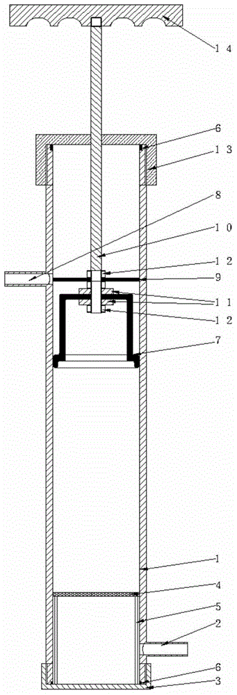
A small transformer oil absorber with filtering function

A technology of transformer oil and oil absorber, which is applied in the direction of transformer/inductor cooling, filtration and separation, chemical instruments and methods, etc. It can solve the problems of inconvenient operation of large-scale oil pumping and oil filtering equipment, surrounding environmental pollution, etc., and achieve guaranteed use value , Guaranteed sealing performance, easy to carry effect

Active Publication Date: 2017-02-01
STATE GRID CORP OF CHINA +1
View PDF5 Cites 0 Cited by
  • Summary
  • Abstract
  • Description
  • Claims
  • Application Information

AI Technical Summary

Problems solved by technology

The traditional method is to use an oil extractor to pump out the transformer oil, and then carry out the oil filtering operation. At the same time, many transformers are located on elevated utility poles, which is not convenient to use large-scale oil pumping and oil filtering equipment for operation, and traditional oil pumping and oil filtering equipment are all For the separate design, the staff may need to perform two operations to complete the oil filtering process, and the surrounding environment may be polluted due to oil leakage and other conditions during the operation

Method used


Image

  • A small transformer oil absorber with filtering function

Examples


Embodiment 1

[0025] Such as figure 1 As shown, a small transformer oil absorber with filtering function is mainly composed of an oil absorber cylinder 1, an oil inlet 2, and an oil outlet 8. The upper part of the oil absorber cylinder 1 is provided with a top cover 13, so The lower part of the oil absorber cylinder 1 is provided with a bottom cover 3, and the lower part of the oil absorber cylinder 1 is provided with an oil filter 4, the oil filter 4 is located above the oil inlet 2, and the oil absorber cylinder 1 A central shaft 10 is installed inside, the upper end of the central shaft 10 runs through the middle of the top cover 13 , and the lower end of the central shaft 10 is connected with a rubber cup 7 . The worker connects the oil inlet 2 to the oil pipe, and pulls the center shaft upwards, so that the oil can be sucked into the oil absorber cylinder 1. When the oil enters the oil absorber cylinder 1, it will pass through the oil filter 4 during the upward suction process. , so t...

Embodiment 2

[0027] In order to better realize the present invention, it is convenient to fix the rubber cup 7. In this embodiment, on the basis of Embodiment 1, the upper and lower sides of the rubber cup 7 are provided with fixed rings 11, and the fixed rings 11 are fixed by bolts. 12 is fixed on the axis 10. By using the fixing ring 11 and the bolt 12 to fix the rubber cup 7, the rubber cup can be prevented from moving up and down along the central axis 10, and the bolt 12 and the fixing ring 11 can seal between the rubber cup 7 and the central shaft 10, Prevent air leakage, which affects oil absorption efficiency. Other parts of this embodiment are the same as those of Embodiment 1, and will not be repeated here.

Embodiment 3

[0029] In order to better realize the present invention and improve the sealing performance of the rubber cup 7, in this embodiment, on the basis of Embodiment 2, a sealing horizontal plate 9 is arranged on the upper part of the fixing ring 11, and the sealing horizontal plate 9 passes through The bolt 12 is fixed on the central shaft 10 . By adopting the sealing horizontal plate 9 to seal the rubber cup 7, air leakage can be prevented and the oil absorption efficiency can be improved. Other parts of this embodiment are the same as those of Embodiment 2, and will not be repeated here.


PUM


Abstract

The invention discloses a small transformer oil suction device with a filtering function. The small transformer oil suction device is mainly composed of an oil suction device tube body, an oil inlet and an oil outlet. A top seal cover is arranged on the upper portion of the oil suction device tube body, a bottom seal cover is arranged on the lower portion of the oil suction device tube body, and an oil filter net is arranged on the lower portion of the oil suction device tube body and located above the oil inlet. A centre shaft is installed inside the oil suction device tube body, the upper end of the centre shaft penetrates through the middle of the top seal cover, and the lower end of the centre shaft is connected with a rubber packing cup. While sucked, oil is filtered, and therefore accidents caused by oil quality problems are prevented. Meanwhile, the small transformer oil suction device is simple in design, convenient to use, good in sealing performance and convenient to carry, and the components are convenient to replace.

Description

technical field [0001] The invention relates to the field of electric equipment, in particular to a small transformer oil absorber with filtering function. Background technique [0002] When the transformer runs for a long time, certain gas, moisture and other impurities will be produced in the transformer oil. The main function of transformer oil in the transformer is to dissipate heat. The gap of the oil passage of the heat sink of the transformer is small. If the oil is dirty, it will block the heat dissipation oil passage, affect the heat dissipation effect, seriously cause the transformer to heat up, and even cause major accidents such as explosion and fire. This affects the insulation and heat dissipation properties of the transformer oil. Therefore, oil filtering measures should be adopted. The traditional method is to use an oil extractor to pump out the transformer oil, and then carry out the oil filtering operation. At the same time, many transformers are located...

Claims


Application Information

Patent Timeline
Patent Type & Authority Patents(China)
IPC IPC(8): H01F27/14B01D35/02
Inventor 王宇张志
Owner STATE GRID CORP OF CHINA
Why Eureka
Try Eureka