Capacitive RF MEMS switch

A capacitive and switching technology, applied in circuits, relays, electrical components, etc., can solve the problems of short switching time, high driving voltage, low energy consumption, etc., and achieve the effect of reducing the elastic coefficient and driving voltage

Inactive Publication Date: 2014-07-23
SUZHOU KUEN ELECTRONICS TECH
View PDF8 Cites 3 Cited by
  • Summary
  • Abstract
  • Description
  • Claims
  • Application Information

AI Technical Summary

Problems solved by technology

[0002] RF MEMS switches usually use electrostatic actuation technology, which has low power consumption (several microwatts), simple bias network, and short switching time (small electrode size, film layer Thin) and other advantages, but there are also disadvantages such as high driving voltage (30-80 V)

Method used


Image

  • Capacitive RF MEMS switch
  • Capacitive RF MEMS switch
  • Capacitive RF MEMS switch

Examples


Embodiment Construction

[0012] The design will be further described below in conjunction with the accompanying drawings of the description.

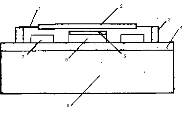
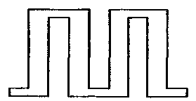
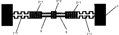
[0013] Such as figure 1 --Shown in 3, a capacitive RF MEMS switch includes a substrate 8, a buffer dielectric layer 4 on the substrate, a ground wire 7, a coplanar waveguide transmission line 6, an anchor point 3, an insulating dielectric layer 5, and an elastic fold The beam 1, the upper electrode 2, the ground wire 7, the coplanar waveguide transmission line 6, and the anchor point 3 are set on the buffer medium layer 4, the insulating medium layer 5 is covered on the coplanar waveguide transmission line 6, and the elastic One end of the folding beam 1 is connected to the anchor point 3, and the other end is connected to the upper electrode 2. There is a gap between the upper electrode 2 and the insulating medium layer 5. It is characterized in that: the bending shape of the elastic folding beam 1 is n-shaped, curved The number is 2, and the number of s...


PUM


Abstract

A capacitive RF MEMS switch comprises a substrate, a buffer dielectric layer on the substrate, grounding leads, a coplanar waveguide transmission line, anchor points, an insulation dielectric layer, elastic folded beams and an upper electrode. The grounding leads, the coplanar waveguide transmission line and the anchor points are arranged on the buffer dielectric layer, the coplanar waveguide transmission line is covered with the insulation dielectric layer, one ends of the elastic folded beams are connected with the anchor points, the other ends of the elastic folded beams are connected with the upper electrode, a clearance is reserved between the upper electrode and the insulation dielectric layer, the elastic folded beams are bent to be in an n shape, the bending number is two, and the set number is two. The upper electrode comprises a drive electrode plate and a capacitive upper electrode plate, and the drive electrode plate and the capacitive upper electrode plate are connected through dual straight beams. The supporting structure of the upper electrode plate is optimized, the elastic coefficient of a microbridge is effectively lowered, and the drive voltage of the capacitive RF MEMS switch is lowered. Experiments show that the drive voltage can be lower than 3 V.

Description

technical field [0001] This design involves a capacitive RF MEMS switch, which belongs to the field of radio frequency technology. Background technique [0002] RF MEMS switches usually use electrostatic drive technology, which has the advantages of low energy consumption (several microwatts), simple bias network, and short switching time (small electrode size, thin film layer), but there are also high drive voltages (30-80 V) and other shortcomings. The operating voltage of mobile communication equipment is generally much lower. For example, the operating voltage of a mobile phone is 3.3 V, and an up-converter needs to be added. In addition, the lifetime of the capacitive RF MEMS switch has a great relationship with the driving voltage. For every 5-7V drop in the driving voltage, the lifetime of the switch can be extended by 10 years. How to reduce the driving voltage is not only related to the material of the switch, but also closely related to the geometric structure ...

Claims


Application Information

Patent Timeline
Patent Type & Authority Applications(China)
IPC IPC(8): H01H59/00
Inventor 杨俊民
Owner SUZHOU KUEN ELECTRONICS TECH
Why Eureka
Try Eureka