Parallel capacitor switch

A capacitive switch, parallel technology, applied in the direction of circuits, relays, electrical components, etc., can solve problems such as large driving voltage

Active Publication Date: 2020-02-28
BEIJING UNIV OF POSTS & TELECOMM
View PDF7 Cites 1 Cited by
  • Summary
  • Abstract
  • Description
  • Claims
  • Application Information

AI Technical Summary

Problems solved by technology

[0004] The purpose of the embodiments of the present invention is to provide a parallel capacitive switch to solve the problem

Method used


Image

  • Parallel capacitor switch
  • Parallel capacitor switch
  • Parallel capacitor switch

Examples


Embodiment Construction

[0033] The following will clearly and completely describe the technical solutions in the embodiments of the present invention with reference to the accompanying drawings in the embodiments of the present invention. Obviously, the described embodiments are only some, not all, embodiments of the present invention. Based on the embodiments of the present invention, all other embodiments obtained by persons of ordinary skill in the art without making creative efforts belong to the protection scope of the present invention.

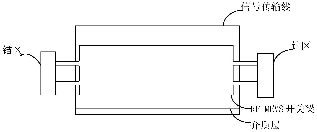
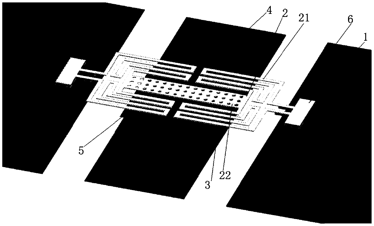
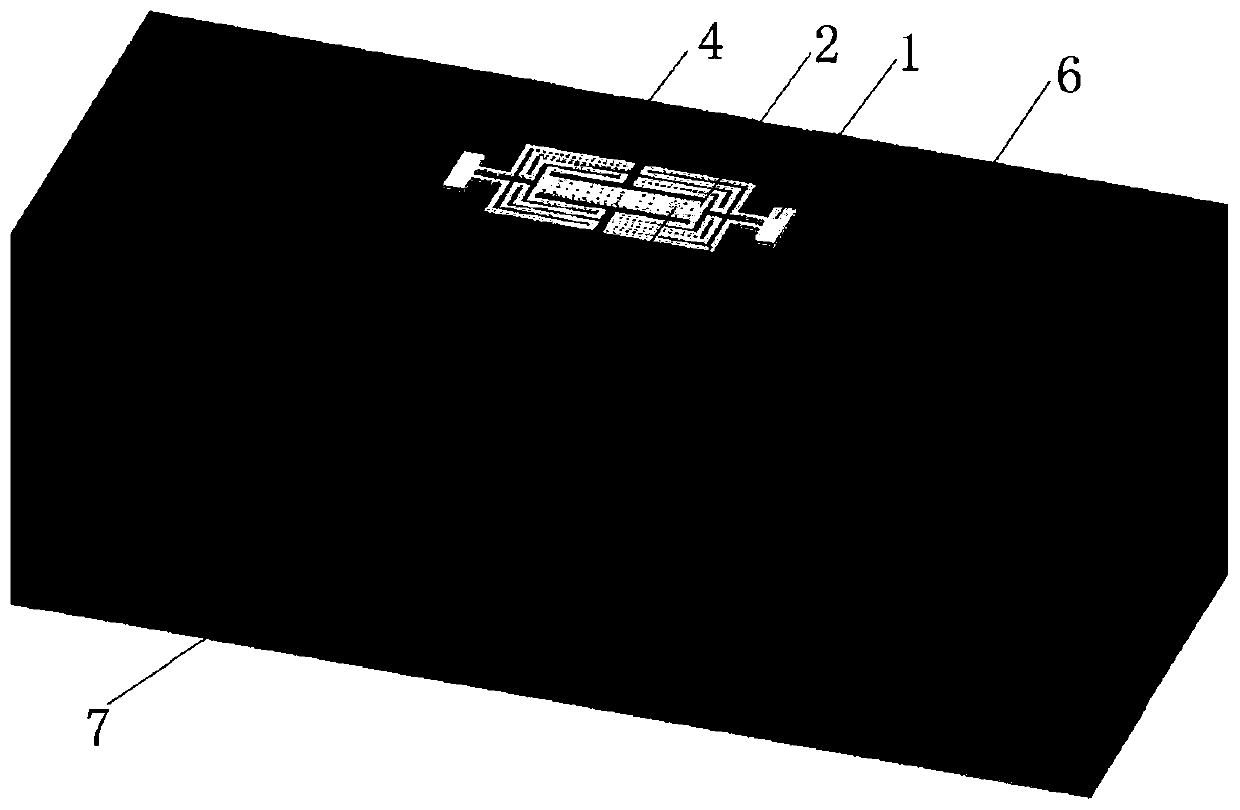
[0034] In order to solve the problem that a large driving voltage is required when the RF MEMS switch beam is moved down and the radio frequency signal is blocked, the embodiment of the present invention provides a parallel capacitive switch, refer to figure 2 , The parallel capacitive switch provided by the embodiment of the present invention includes: an anchor region 1 , an RF MEMS switch beam 2 , a dielectric layer 3 , a signal transmission line 4 , a floa...


PUM

PropertyMeasurementUnit
Thicknessaaaaaaaaaa

Abstract

The embodiment of the invention discloses a parallel capacitor switch, which comprises two anchor zones, an RF MEMS switch beam, a dielectric layer and a signal transmission line. The RF MEMS switch beam includes a plurality of snakelike structured springs and intermediate beams. The two anchor zones are respectively fixed on both sides of the RF MEMS switch beam. The dielectric lay is located between the RF MEMS switch beam and the signal transmission line. The elasticity coefficient of the multiple snakelike structured springs is less than a preset elasticity coefficient threshold. One end of the snakelike structured springs is connected with the anchor zones, and the other end of the snakelike structured springs is connected with the intermediate beams. When a driving voltage accesses to the RF MEMS switch beam, the intermediate beams move downward to drive multiple snakelike structured springs to twist until the intermediate beams and the multiple snakelike structured springs comeinto contact with the dielectric layer, so that signals transmitted by a signal transmission line are coupled to the ground wire.

Description

technical field [0001] The invention relates to the technical field of electronic switches, in particular to a parallel capacitor switch. Background technique [0002] At present, RF MEMS (Radio Frequency Microelectro Mechanical Systems, radio frequency microelectromechanical systems) switch has become a hot spot in scientific and technological research. The switch has many advantages, such as low insertion energy consumption, high capacitance ratio, low power consumption, etc. Therefore, RF MEMS switches are widely used in many fields. have wide applications. In current technology, such as figure 1 As shown, the RFMEMS switch includes an RF MEMS switch beam, an anchor region, a dielectric layer and a signal transmission line. The anchor area is fixed at both ends of the RF MEMS switch beam, and the dielectric layer is located between the RF MEMS switch beam and the signal transmission line. The working principle of the RF MEMS switch is: before the RF MEMS switch beam is...

Claims


Application Information

Patent Timeline
IPC IPC(8): H01H59/00H01P1/10
CPCH01H59/0009H01P1/10
Inventor 韩可邓中亮刘义彬王钰程李务雨
Owner BEIJING UNIV OF POSTS & TELECOMM
Why Eureka
Try Eureka