
Copper wire welding clamp

A technology of welding fixtures and copper wires, which is applied in connection, line/collector parts, electrical components, etc., can solve problems affecting the safe use of transformers, irregular welding joints, affecting welding quality and appearance, etc., achieving simple structure, Copper wire joints are firm and smooth, satisfying the effect of welding quality

Inactive Publication Date: 2014-07-23
KUNSHAN DAGONG ELECTRONICS
View PDF6 Cites 2 Cited by
  • Summary
  • Abstract
  • Description
  • Claims
  • Application Information

AI Technical Summary

Problems solved by technology

[0003] Most of the existing copper wire welding is random and random joint welding, so that the welding joints appear irregular, which affects the welding quality and appearance, and in severe cases, it also affects the safe use of the transformer

Method used


Image

  • Copper wire welding clamp
  • Copper wire welding clamp

Examples


Embodiment Construction

[0016] The present invention will be further described below with reference to the accompanying drawings.

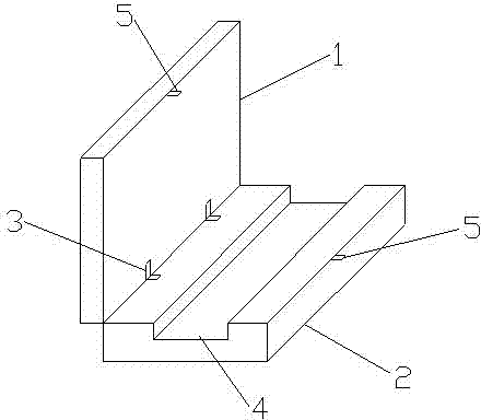
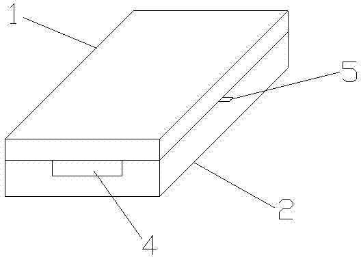
[0017] like figure 1 and figure 2 As shown, a copper wire welding jig includes an upper clamping block 1 and a lower clamping block 2, the two are fastened to each other and arranged in parallel, and are connected at the same end by a movable connector 3, and in addition, a middle part of the lower clamping block 2 is opened. There are copper wire placement grooves 4 that communicate with each other before and after, and the height of the copper wire placement groove 4 is the diameter of the copper wire. The other ends of the upper clamping block 1 and the lower clamping block 2 relative to the movable connecting member 3 are also provided with a buckling member 5 . The movable connecting piece 3 of the present invention is a hinge connecting piece; the clasping piece 5 is a locking structure, which is composed of a locking tongue and a base.

[0018] The innovation ...


PUM


Abstract

The invention discloses a copper wire welding clamp which comprises an upper clamping block and a lower clamping block. The upper clamping block and the lower clamping block are buckled with each other and are arranged in parallel. The same ends of the upper clamping block and the lower clamping block are connected through a movable connecting piece. A front-back-through copper wire mounting groove is formed in the middle of the lower clamping block. The height of the copper wire mounting groove is equal to the diameter size of a copper wire. Buckling pieces which are arranged at the other ends, opposite to the ends of the movable connecting piece, of the upper clamping block and the lower clamping block are further included. According to the copper wire welding clamp, the copper wire is placed in the groove visually, smooth arraying of copper wires is guaranteed, the problem that time and labor are wasted during a copper wire hole punching process, and bending may happen to the copper wires during a hole punching process is avoided, placing efficiency is improved, firmness and smoothness of a welded copper wire connector are guaranteed, the requirement of welding quality is met, and the copper wire welding clamp has the advantages of being simple in structure, convenient to use, visual, reliable and low in cost.

Description

technical field [0001] The invention relates to a fixture, in particular to a copper wire welding fixture. Background technique [0002] With the rapid development of power technology and electronic equipment, the voltage level and capacity of transformers are constantly increasing, which often involves the welding of copper wires. [0003] In the existing copper wire welding, the joints are mostly welded at random, so that the welded joints are in an irregular state, thereby affecting the welding quality and appearance, and in serious cases, the safe use of the transformer. SUMMARY OF THE INVENTION [0004] The main purpose of the present invention is to overcome the deficiencies in the prior art and provide a copper wire welding jig, which is especially suitable for the welding of multi-strand copper wires. [0005] The technical problem to be solved by the present invention is to provide a copper wire welding fixture with simple structure, convenient use, low productio...

Claims


Application Information

Patent Timeline
IPC IPC(8): H01R43/02
Inventor 任育文
Owner KUNSHAN DAGONG ELECTRONICS
Learn More