
A wire feeding system for a welding machine head

A technology of wire feeding system and welding head, which is applied in the direction of welding equipment, welding accessories, welding rod characteristics, etc., can solve the problem that the processing and manufacturing requirements of the high temperature gas-cooled reactor project cannot be fully met, the weld seam cannot meet the quality requirements of nuclear power products, and the weld seam Small groove and other problems, to achieve no dead angle monitoring, good protection effect, and ensure the effect of welding quality

Active Publication Date: 2018-01-30
HARBIN ELECTRIC CORP QINHUANGDAO HEAVY EQUIP
View PDF7 Cites 0 Cited by
  • Summary
  • Abstract
  • Description
  • Claims
  • Application Information

AI Technical Summary

Problems solved by technology

According to the manufacturing technical requirements of nuclear power products, the existing equipment structure and functions cannot fully meet the processing and manufacturing requirements of the high-temperature gas-cooled reactor project, especially the all-position welding and 2G position welding of the high-temperature gas-cooled reactor evaporator assembly welds are industry-leading A big problem is that the groove of the weld is small and the weld bead is deep, and its quality requirements for welding are extremely strict. The weld obtained by welding with ordinary welding equipment cannot meet the quality requirements of nuclear power products. Therefore, there is an urgent need for a New welding equipment that can solve the above problems

Method used


Image

  • A wire feeding system for a welding machine head
  • A wire feeding system for a welding machine head
  • A wire feeding system for a welding machine head

Examples


Embodiment Construction

[0087] The present invention will be further described in detail through the drawings and examples below. Through these descriptions, the features and advantages of the present invention will become more apparent.

[0088] The word "exemplary" is used exclusively herein to mean "serving as an example, embodiment, or illustration." Any embodiment described herein as "exemplary" is not necessarily to be construed as superior or better than other embodiments. While various aspects of the embodiments are shown in drawings, the drawings are not necessarily drawn to scale unless specifically indicated.

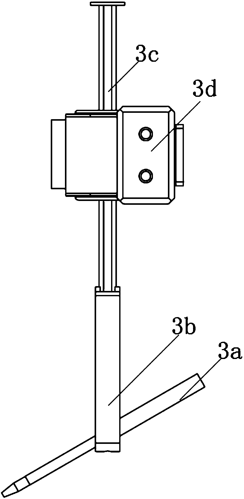
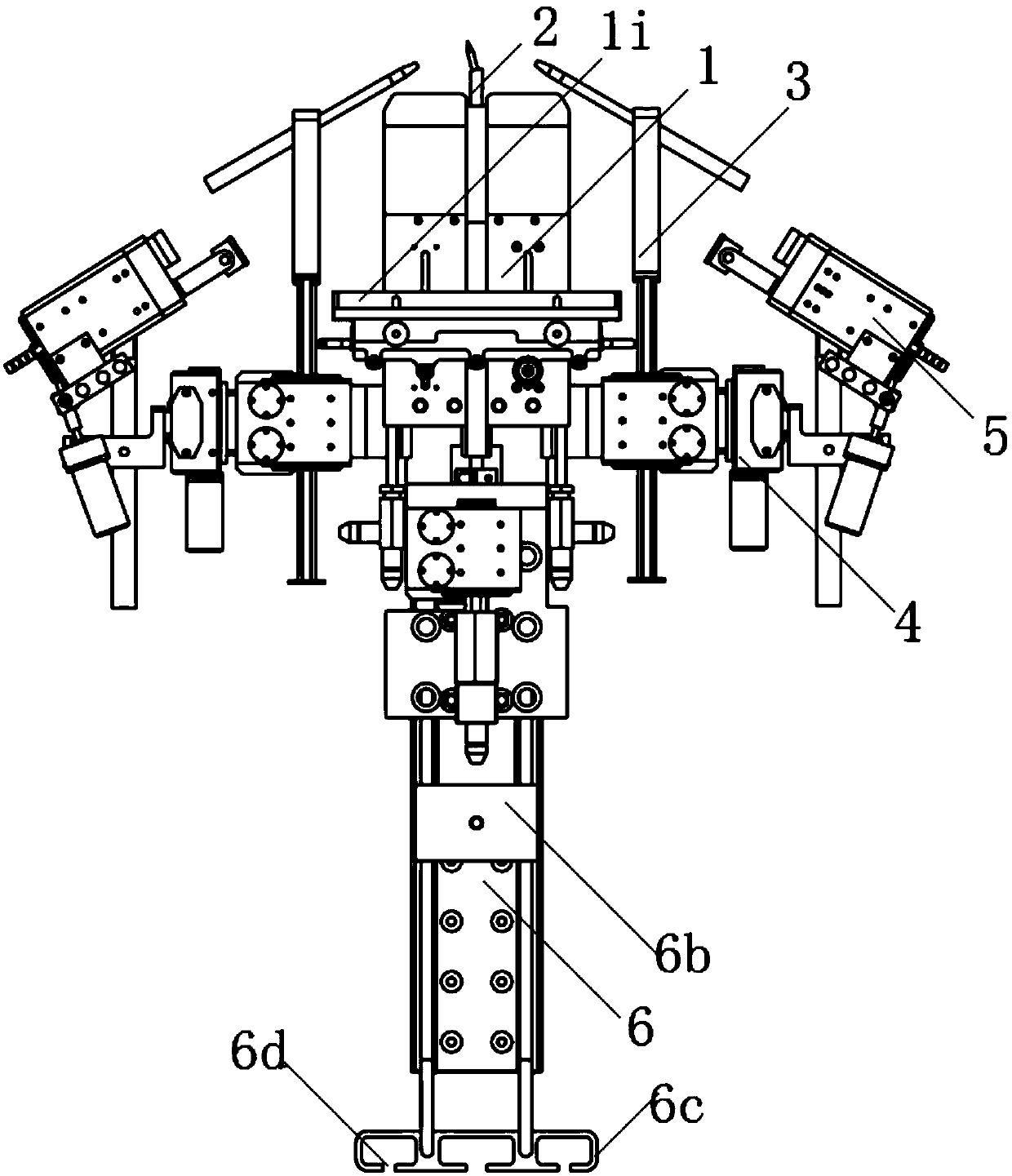
[0089] The wire feeding system of the welding head provided according to the present invention, such as figure 1 and figure 2 As shown in , the wire feeding system includes a wire feeding rod 3a, a wire feeding rod bracket 3b and an adjusting screw 3c, wherein one end of the wire feeding rod bracket is fixed at a predetermined angle with the wire feeding rod as a whole, and the ...


PUM


Abstract

The invention discloses a wire feeding system for a welding head. The wire feeding system comprises a wire feeding rod, a wire feeding rod support and an adjusting screw, wherein one end of the wire feeding rod support and the wire feeding rod are fixedly connected to be a whole at a predetermined angle, the other end of the wire feeding rod is fixedly connected with the adjusting screw, and thus the wire feeding rod is driven by the rotatable adjusting screw to rotate. The rotating angle of the wire feeding rod is small, so that it is convenient to control a welding wire to move in a small range, and accordingly the relative position between the welding wire and a molten pool is adjusted. The welding head is infinitely rotary, the wire feeding system on the welding head can adjust the relative position relations of the molten pool and the welding wire according to concrete working conditions of a circumferential weld joint around the welding head in the rotating process of the welding head, and thus the welding quality can meet the quality requirements of nuclear power products.

Description

technical field [0001] The invention relates to the technical field of welding equipment, in particular to a wire feeding system of a welding machine head. Background technique [0002] The high-temperature gas-cooled reactor evaporator project has not been processed and manufactured by any enterprise in the world, so the high-temperature gas-cooled reactor evaporator project has been listed as a major national development project. According to the manufacturing technical requirements of nuclear power products, the existing equipment structure and functions cannot fully meet the processing and manufacturing requirements of the high-temperature gas-cooled reactor project, especially the all-position welding and 2G position welding of the high-temperature gas-cooled reactor evaporator assembly welds are industry-leading A big problem is that the groove of the weld is small and the weld bead is deep, and its quality requirements for welding are extremely strict. The weld obtain...

Claims


Application Information

Patent Timeline
Patent Type & Authority Patents(China)
IPC IPC(8): B23K9/133B23K9/167B23K9/028B23K9/28B23K9/26B23K9/29B23K9/32
CPCB23K9/028B23K9/133B23K9/164B23K9/167B23K9/26B23K9/28B23K9/296B23K9/325
Inventor 李向国沈诗颂郭志平王彦波蒋海峰
Owner HARBIN ELECTRIC CORP QINHUANGDAO HEAVY EQUIP
Learn More