Inkjet recording device

An inkjet recording and recording head technology, applied in printing and other directions, can solve the problems of inability to effectively suppress residual vibration and unstable continuous ink ejection, and achieve the effects of preventing residual vibration, preventing ink penetration, and stably ejecting

Active Publication Date: 2014-07-23
MIMAKI ENG
View PDF6 Cites 4 Cited by
  • Summary
  • Abstract
  • Description
  • Claims
  • Application Information

AI Technical Summary

Problems solved by technology

[0012] The inventors of the present invention have studied to suppress residual vibration in the case of relatively low-viscosity ink, but the following problems arise: when such an ink is used to execute the driving method shown in Patent Document 1, the residual vibration cannot be effectively suppressed, Continuous ejection of ink is unstable, and ink seeps through the opening of the nozzle

Method used


Image

  • Inkjet recording device
  • Inkjet recording device
  • Inkjet recording device

Examples


Embodiment Construction

[0045] Hereinafter, preferred embodiments of the present invention will be described with reference to the drawings.

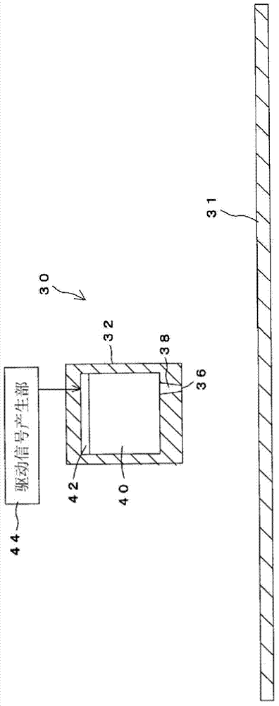
[0046] exist figure 1 A schematic diagram of an inkjet recording apparatus is shown in .

[0047] The inkjet recording device 30 is a device that performs printing on a medium 31 by jetting ink, and includes a recording head 32 that ejects ink to the medium 31 , and an ink tank (not shown) that stores ink supplied to the recording head 32 .

[0048] The recording head 32 includes a nozzle 38 formed with an opening 36 for ejecting ink, and a pressure chamber 40 for accommodating ink. In addition, a part of the wall surface constituting the pressure chamber 40 is formed by the piezoelectric element 42 . The piezoelectric element 42 is deformed by applying a predetermined voltage, and the deformation of the piezoelectric element 42 changes the volume of the pressure chamber 40 so that the ink contained in the pressure chamber 40 can be ejected from the nozzle ...


PUM


Abstract

Provided is an inkjet recording device that, no matter what sort of ink the ink is, prevents residual oscillation of the ink, thereby preventing permeation of the ink at an opening section, and can stably cause the continuous discharge of the ink. The inkjet recording device (30) is equipped with: a recording head (32) at which a nozzle (38) is formed having a pressure chamber (40), which houses ink, and an opening section (36) that causes the discharge of ink and interconnects with the pressure chamber (40); a piezoelectric element (42) configuring a portion of the pressure chamber (40); and a drive signal generation unit (44) that inputs a drive signal to the piezoelectric element (42), altering the volume of the pressure chamber (40). The drive signal generation unit (44) generates the drive signal in a manner so as to cause the execution of: a first expansion step for causing the expansion of the pressure chamber (40); after the first expansion step, a first contraction step for causing the contraction of the pressure chamber to cause the discharge of ink; and after the first contraction step, a second contraction step for causing the contraction of the pressure chamber at a timing at which a meniscus is pulled in the reverse direction from the direction of discharge. The drive signal output by the drive signal generation unit (44) is set in a manner so that the electrical potential at the endpoint of the second contraction step is positioned in a range on the reverse side from the electrical potential at the starting point of the first expansion step, and is set in a manner so that the electrical potential at the starting point of the first expansion step is approximately the same as the electrical potential at the starting point of the second contraction step.

Description

technical field [0001] The present invention relates to an inkjet recording device having a recording head which, when ejecting ink from the recording head, deforms a part of a pressure chamber communicating with a nozzle to eject ink. Background technique [0002] In an inkjet recording device that ejects ink from a recording head to a medium, the recording head is provided with a nozzle having a plurality of minute openings and a pressure chamber communicating with the nozzle. [0003] A part of the wall surface of the pressure chamber is formed of a piezoelectric element, and the volume of the pressure chamber can be changed by vibrating the piezoelectric element by applying a voltage to the piezoelectric element. [0004] exist Figure 5 An example of a common voltage applied to a piezoelectric element is shown in . [0005] As a result, first, the voltage applied to the piezoelectric element is reduced from the voltage VH at which the pressure chamber is in a contracte...

Claims


Application Information

Patent Timeline
Patent Type & Authority Applications(China)
IPC IPC(8): B41J2/01B41J2/045B41J2/055
CPCB41J2/04581B41J2/04588B41J2/04596B41J2/04525B41J2/04541
Inventor 柳泽昇太
Owner MIMAKI ENG
Why Eureka
Try Eureka