Tube purification unit for sustainable production of evaporable materials

A continuous production, tubular technology, applied in chemical instruments and methods, separation methods, sublimation, etc., can solve the problems of difficult industrialization, low, and difficult to sustain production efficiency, save time and energy, increase revenue, High purity and stable effect

Active Publication Date: 2015-12-30
SHANGHAI UNIV
View PDF5 Cites 0 Cited by
  • Summary
  • Abstract
  • Description
  • Claims
  • Application Information

AI Technical Summary

Problems solved by technology

Although this method is very effective, it must be cooled and opened after each feeding and purification to take out the materials of each component and reload, so it is difficult to continue the production efficiency and realize industrialization.
This makes the price of high-purity materials remain high, which affects the development of the OLED industry.

Method used


Image

  • Tube purification unit for sustainable production of evaporable materials
  • Tube purification unit for sustainable production of evaporable materials
  • Tube purification unit for sustainable production of evaporable materials

Examples


Embodiment 1

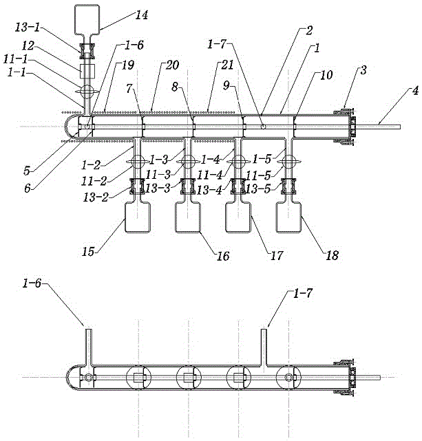
[0029] Such as figure 1 As shown, a tubular purification device for sustainable production of evaporable materials includes an outer tube 1, an inner tube 2, a vacuum head 3, a push-pull rod 4, a leveling disc 5, a first scraping disc 6 with a gap, The second scraping disc 7, the third scraping disc 8, the fourth scraping disc 9, and the air-blocking disc 10; the outer tube 1 has a feed tube 1-1, a first discharge tube 1-2, and a first discharge tube 1-2. Two discharge pipes 1-3, the third discharge pipe 1-4, the fourth discharge pipe 1-5, the air inlet pipe 1-6 and the exhaust pipe 1-7, the diameter of the inner pipe 2 is smaller than the outer pipe 1 , which can fit tightly inside the outer tube 1, and have corresponding openings at each outlet of the outer tube 1; The push-pull rod 4 is connected to the push-pull rod 4 in turn with a leveling disc 5, a first scraper disc 6, a second scraper disc 7, a third scraper disc 8, a fourth scraper disc 9, and an air barrier disc 1...

Embodiment 2

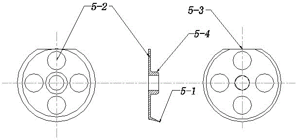
[0032] Such as Figure 2 to Figure 5 As shown, the screed disc 5 described in this embodiment is made of stainless steel, molybdenum, titanium or high-temperature alloy; there is a first connection sleeve hole 5-4 connecting the push-pull rod 4 in the middle of the screed disc 5, There is a first knife edge 5-1 close to the inner tube 2 on the periphery, a number of first vent holes 5-2 inside, and a first notch 5-3 on the top. The position of the first notch 5-3 is consistent with the first scraping material The second notch 6-5 of the disc 6 corresponds.

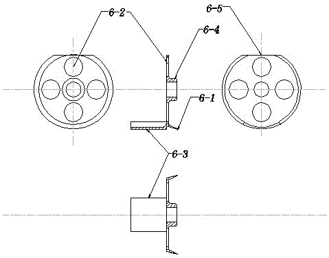
[0033] The notched first scraping disc 6 is made of stainless steel, molybdenum, titanium or high-temperature alloy; there is a second connecting sleeve hole 6-4 connecting the push-pull rod 4 in the middle of the first scraping disc 6, There is a second knife edge 6-1 close to the inner tube 2 on the periphery, a number of second ventilation holes 6-2 inside, and a feeding tube 1-1 on the inner tube 2 on the other side o...

Embodiment 3

[0037] Such as Image 6 As shown, the purification process of this embodiment is basically the same as that of Embodiment 1, the difference is that the feed device 12 consists of a rotary column valve body 12-1-1, a columnar valve core 12-1-2, and The charging cavity 12-1-3 and the connecting pipe 12-1-4 are composed. The charging cavity 12-1-3 is placed in the columnar valve core 12-1-2 and one side is closed, and the rotating columnar valve core 12- 1-2. When the charging cavity 12-1-3 is aligned with the charging port 12-1-5 above the rotary column valve body 12-1-1, the powder material falls into the charging cavity 12-1- 3, and then rotate the cylindrical valve core 12-1-2180 degrees so that the charging cavity 12-1-3 is aligned with the discharge port 12-1-6 below the rotating column valve body 12-1-1, The powder material enters the feeding pipe 1-1 through the connecting pipe 12-1-4.


PUM


Abstract

The invention relates to a tubular purification device for sustainable production of evaporable materials, which consists of an outer tube with a feed pipe, a plurality of discharge pipes, an air inlet pipe and an air extraction pipe, and an outer pipe with a diameter slightly smaller than the outer pipe can be sleeved on the outside The inside of the tube is tightly fitted and has corresponding openings at each outlet of the outer tube. The vacuum head connected to the outer tube has a vacuum seal in the center of the vacuum head that can be pushed, pulled and rotated. The push-pull rod is also connected with a scraper plate with a notch on the even material disc, 3 scraper plates and a gas-blocking plate, and a vacuum valve feed device is connected to the feed port of the outer tube. The vacuum joint is connected to the raw material bottle , there are vacuum valves and vacuum joints connected to the four outlets under the outer tube, which are connected with the corresponding non-volatile material bottles, concentrated material bottles, medium temperature material bottles, and low temperature material bottles. There are three independent outlets outside the outer tube. Temperature-controlled heating furnace wire to form three temperature zones.

Description

technical field [0001] The invention relates to a tubular purification device for sustainable production of various evaporable organic materials, such as organic electroluminescent materials, organic thin film solar cell materials, organic thin film transistor materials, etc., and inorganic materials with relatively low evaporation temperatures. Background technique [0002] It is a very effective method to use different evaporation temperatures of various materials to purify materials, especially in organic materials, the law that the evaporation temperature changes with the change of parameters such as different chemical components, structures, molecular weights, etc. can be used at different temperatures. Purification by evaporation has become a very effective method for solid materials such as organic electroluminescence (OLED), organic solar cells (OPV), organic thin film transistors (OTFT), etc. At present, the commonly used method is to use a tubular purification devi...

Claims


Application Information

Patent Timeline
Patent Type & Authority Patents(China)
IPC IPC(8): B01D7/00
Inventor 张建华张志林王子兴蒋雪茵
Owner SHANGHAI UNIV
Why Eureka
Try Eureka