Cooling device for gear forging

A cooling device and gear forging technology, applied in heating/cooling equipment, forging/pressing/hammer devices, manufacturing tools, etc., can solve the problems of lowering product quality, scrapped molds, mold deformation, etc., to improve quality and prolong service life , the effect of simple structure

Active Publication Date: 2015-11-18
东华链条兴化有限公司
View PDF6 Cites 1 Cited by
  • Summary
  • Abstract
  • Description
  • Claims
  • Application Information

AI Technical Summary

Problems solved by technology

The traditional cooling method is to use a hand-held spray gun to cool the mold, but this method has the following problems: first, the direct use of water spraying method is easy to cause deformation of the mold itself, which leads to the scrapping of the mold and waste; second, the forging process The fine chips or dust generated in the process will stay in the mold due to the treatment of atomized water, which will reduce the quality of the product

Method used


Image

  • Cooling device for gear forging

Examples


Embodiment Construction

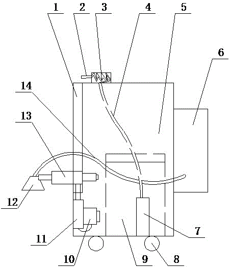
[0015] The present invention will be further described below in conjunction with the accompanying drawings.

[0016] Such as figure 1 As shown, a cooling device for gear forging according to the present invention includes a main control box 5, and a vertical rail 1 is arranged on the left side of the main control box 5; Cylinder A13, the cylinder shaft end of the cylinder A13 is provided with a trumpet-shaped blower port 12; a motor A is arranged on the left side wall of the main control box 5, and the motor A is connected to the cylinder A13 through a wire to drive the cylinder shaft of the cylinder A. Telescopic; the bottom of the left side wall of the main control box 5 is provided with a cylinder B11, the cylinder shaft end of the cylinder B11 is connected with the cylinder body of the cylinder A13; It is connected with the cylinder B11; the right side of the main control box 5 is provided with an air conditioner 6, and the air outlet hose 14 of the air conditioner 6 is c...


PUM


Abstract

The invention relates to the technical field of a forging device, in particular to a cooling device for forging and machining a gear. The cooling device comprises a master control box, wherein the left side surface of the master control box is provided with a vertical rail; the vertical rail is provided with an air cylinder A in the horizontal direction, and a cylinder shaft end head of the air cylinder A is provided with a horn-shaped air blowing nozzle; the left side wall in the master control box is provided with an electric motor A, and the electric motor A is connected with the air cylinder A through a leading wire and drives a cylinder shaft of the air cylinder A to stretch; the bottom part of the left side wall in the master control box is provided with an air cylinder B, and a cylinder shaft end head of the air cylinder B is connected with a cylinder body of the air cylinder A; the right side of the air cylinder B is provided with an electric motor B, and the electric motor B is connected with the air cylinder B through a leading wire; the right side surface of the master control box is provided with an air conditioner, and an air outlet hose of the air conditioner is communicated with the horn-shaped air blowing nozzle. The cooling device disclosed by the invention has the advantages that the structure is simple, the operation is convenient, cooling is carried out in steps, non-deformation of a die is ensured, the service life of the die is prolonged, tiny impurities existing in the die are reduced, and the product quality is increased.

Description

technical field [0001] The invention relates to the technical field of forging equipment, in particular to a cooling device for gear forging. Background technique [0002] Nowadays, more precise mechanical gear components are generally produced by forging. The operation process is to use a forging machine for forging, place the workpiece in the forging die, and use the forging hammer of the forging machine to forge. In the forging process, the forging die itself is in a high temperature state due to thermal conductivity. After a forging is completed, the die needs to be cooled. The traditional cooling method is to use a hand-held spray gun to cool the mold, but this method has the following problems: first, the direct use of water spraying method is easy to cause deformation of the mold itself, which leads to the scrapping of the mold and waste; second, the forging process The fine chips or dust generated in the mold will stay in the mold due to the treatment of atomized w...

Claims


Application Information

Patent Timeline
Patent Type & Authority Patents(China)
IPC IPC(8): B21K29/00
Inventor 赵剑忠
Owner 东华链条兴化有限公司
Why Eureka
Try Eureka