Grinding device and method of crankshaft by one clamping

A crankshaft and grinding technology, which is applied in the field of crankshaft one-time clamping grinding device, can solve the problems of difficult control, cumbersome operation, and low grinding precision, and achieve the effects of high matching precision, avoiding error accumulation, and low device cost

Active Publication Date: 2014-07-30
THYSSENKRUPP ENGINE COMPONENTS (CHINA) CO LTD
View PDF8 Cites 18 Cited by
  • Summary
  • Abstract
  • Description
  • Claims
  • Application Information

AI Technical Summary

Problems solved by technology

[0006] The purpose of the present invention is to overcome the disadvantages of low grinding precision, cumbersome operation and difficult control of existing crankshafts, and provide a crankshaft grinding device and method with one-time clamping. Adopting the technical scheme of the present invention, only one clamping is required to be able to Grinding out all the main journals and connecting rod journals of the crankshaft does not require a complicated numerical control system, and the operation is simple; the main journals and connecting rod journals of the crankshaft are all theoretical cylindrical profiles, which avoids principle errors and improves machining accuracy

Method used


Image

  • Grinding device and method of crankshaft by one clamping
  • Grinding device and method of crankshaft by one clamping
  • Grinding device and method of crankshaft by one clamping

Examples


Embodiment

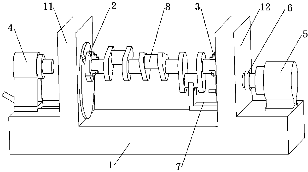
[0042] combine figure 2 , a crankshaft one-time clamping grinding device of the present embodiment includes a frame 1, a left double-rotating shaft positioning disc 2, a right dual-rotating shaft positioning disc 3, a movable indexing mechanism 4, a driving motor 5 and a V-shaped block 7, in,

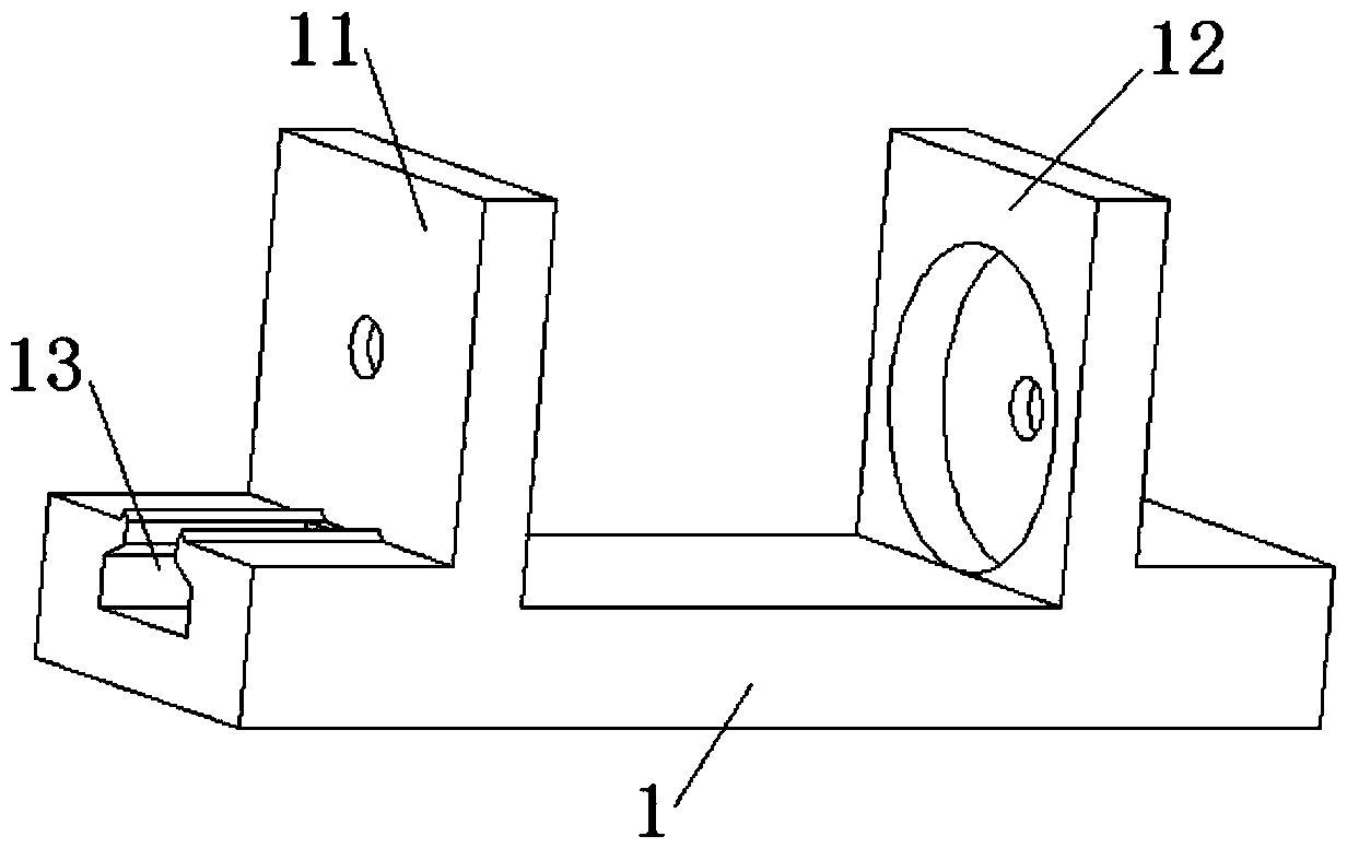
[0043] The frame 1 is vertically provided with a left support plate 11 and a right support plate 12, the left support plate 11 and the right support plate 12 are parallel to each other, and the left support plate 11 and the right support plate 12 are respectively provided with a double-axis positioning disc. Mounting groove; the left double-rotating shaft positioning plate 2 is installed in the mounting groove of the left support plate 11, the right double-rotating shaft positioning plate 3 is installed in the mounting groove of the right supporting plate 12, and the left double-rotating shaft positioning plate 2 and the right double-rotating shaft positioning plate 3 coaxial; the lef...


PUM


Abstract

The invention discloses a grinding device of a crankshaft by one clamping, and belongs to the field of crankshaft grinding. Left and right supporting plates are vertically arranged on a rack, and left and right double rotating shaft positioning discs are respectively and coaxially arranged on the left and right supporting plates and are in a cylindrical shape; crankshaft clamping chucks and V-shaped block mounting grooves are arranged on the left and right double rotating shaft positioning discs, and the crankshaft clamping chucks and the double rotating shaft positioning discs are eccentrically arranged; the eccentric distance is equal to the radius of a crank of the crankshaft, and V-shaped blocks are arranged in the V-shaped block mounting grooves; an output shaft of a driving motor is coaxially connected with the right double rotating shaft positioning disc, and an output shaft of a movable indexing mechanism and the crankshaft clamping chuck on the left double rotating shaft positioning disc are coaxial. The invention also discloses a grinding method of the crankshaft by one clamping. The main journal and the rod journal of the crankshaft can be ground only by one clamping without a complicated numerical control system, and the operation is simple; the main journal and the rod journal of the crankshaft are theoretical cylinders, so that the principle error is avoided, and the machining accuracy is improved.

Description

technical field [0001] The invention relates to a crankshaft grinding device and method, more specifically, to a crankshaft one-time clamping grinding device and method. Background technique [0002] The crankshaft is one of the most important parts of the engine, and its machining accuracy will directly affect the performance of the engine. At the same time, in order to improve the wear resistance of the crankshaft, the main journal and connecting rod journal of the crankshaft have adopted surface quenching, carburizing and other processes to increase their surface hardness. Grinding is necessary for the finishing of these case-hardened parts, and both the crankshaft's main and connecting pin journals must be ground. [0003] There are usually two grinding methods for crankshafts. One is to use concentric fixtures to grind the main journal, and use eccentric fixtures to grind the connecting rod journal. The grinding process is similar to cylindrical grinding. This method ...

Claims


Application Information

Patent Timeline
Patent Type & Authority Applications(China)
IPC IPC(8): B24B5/42B24B41/06
CPCB24B5/421B24B41/06B24B41/065
Inventor 徐波潘光显干为民
Owner THYSSENKRUPP ENGINE COMPONENTS (CHINA) CO LTD
Why Eureka
Try Eureka