Parallel torque coupling type energy-saving workover rig

A torque coupler, coupled technology, applied in drilling equipment, earthwork drilling, drill pipe, etc., can solve problems such as energy waste, reduce costs, reduce energy conversion links, and improve efficiency.

Inactive Publication Date: 2014-07-30
YANTAI UNIV
View PDF9 Cites 3 Cited by
  • Summary
  • Abstract
  • Description
  • Claims
  • Application Information

AI Technical Summary

Problems solved by technology

[0006] In order to overcome the energy waste of conventional workover rigs in the operation of lifting and lowering pipe strings, and at the same time overcome the above-mentioned shortcomings of existing hydraulic energy storage workover rigs, the present invention provides a parallel torque coupling energy-saving workover well rig

Method used


Image

  • Parallel torque coupling type energy-saving workover rig

Examples


Embodiment Construction

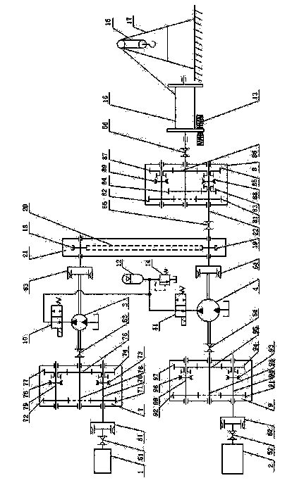
[0015] The present invention will be described in further detail below in conjunction with the accompanying drawings. Referring to the accompanying drawings, the parallel torque coupled energy-saving workover rig includes a small power machine 1, a large power machine 2, a gearbox 8, a drum 15, a traveling block hook 16, a drum brake 13, and a derrick 17. It also includes a first torque Coupler 7, second torque coupler 9, third torque coupler 21, small quantitative hydraulic pump / motor 3, large quantitative hydraulic pump / motor 4, first reversing valve 10, second reversing valve 11, Hydraulic accumulator 12, overflow valve 14. The displacement of the small quantitative hydraulic pump / motor 3 is smaller than the displacement of the large quantitative hydraulic pump / motor 4 . The first shaft 70, the second shaft 78 and the third shaft 79 are installed in the first torque coupling 7; the first gear 71 is fixedly installed on the first shaft 70, the first meshing sleeve 73 is ins...


PUM


Abstract

The invention discloses a parallel torque coupling type energy-saving workover rig. The parallel torque coupling type energy-saving workover rig comprises a small power machine, a large power machine, a first torque coupler, a second torque coupler, a third torque coupler, a hydraulic accumulator, a small quantitative hydraulic pump / motor, a large quantitative hydraulic pump / motor, a gearbox, a roller and the other parts, wherein the small power machine is connected with a shaft of the small quantitative hydraulic pump / motor through the first torque coupler; the large power machine is connected with a shaft of the large quantitative hydraulic pump / motor through the second torque coupler; the shafts of the small quantitative hydraulic pump / motor and the large quantitative hydraulic pump / motor are respectively connected with a chain wheel of the third torque coupler through clutches. Compared to the commonly used conventional workover jig, the power of the power machine can be reduced to 1 / 4 of the conventional workover jig, and further the gravitational potential energy released when the tubular column is put down can be recovered. The roller, the derrick, the gearbox and the other parts of the conventional workover jig are remained, and only the quantitative hydraulic pumps / motors, hydraulic accumulator and the other parts are added on the conventional workover jig, so that the cost is low.

Description

technical field [0001] The invention relates to workover equipment in the petroleum and natural gas industries, in particular to a parallel torque coupling energy-saving workover machine. Background technique [0002] One of the most common operations of workover rigs is the operation of raising and lowering pipe strings. The operation of the lifting string is an intermittent cycle process. The workover rig spends about 1 / 4 of the entire lifting cycle, while the time for auxiliary operations such as shackles and placing single strings takes up 3 / 4. Motorized hoisting strings require a power engine to work with high power, while auxiliary operations such as shackles and placement of single pipes require a power machine to work with low power. Conventional workover rigs have relatively large installed power in order to meet the needs of rapid lifting of pipe strings. The high-power power machine works under low power most of the time, the economy is poor, and the power mach...

Claims


Application Information

Patent Timeline
Patent Type & Authority Applications(China)
IPC IPC(8): E21B19/00
Inventor 张路军
Owner YANTAI UNIV
Why Eureka
Try Eureka