Conveying chain plate of vegetable dehydrating device

A conveyor chain plate, vegetable dehydration technology, applied in the direction of drying solid materials, applications, food processing, etc., to achieve the effect of improving efficiency and easy discharge

Inactive Publication Date: 2014-07-30
罗静
View PDF1 Cites 0 Cited by
  • Summary
  • Abstract
  • Description
  • Claims
  • Application Information

AI Technical Summary

Problems solved by technology

The technical problem of this kind of conveyor chain plate is: the ventilation effect of the through hole is like a ventilation seam, so it is necessary to improve the existing conveyor chain plate

Method used


Image

  • Conveying chain plate of vegetable dehydrating device
  • Conveying chain plate of vegetable dehydrating device
  • Conveying chain plate of vegetable dehydrating device

Examples


Embodiment 1

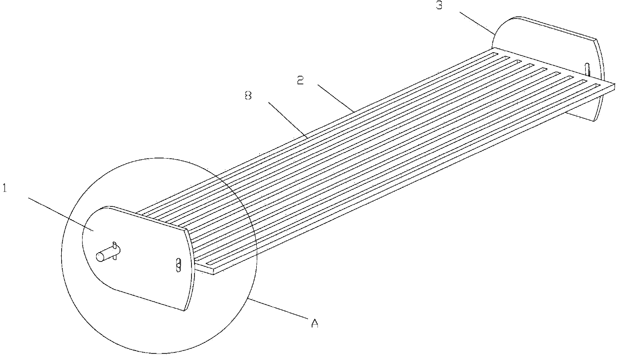
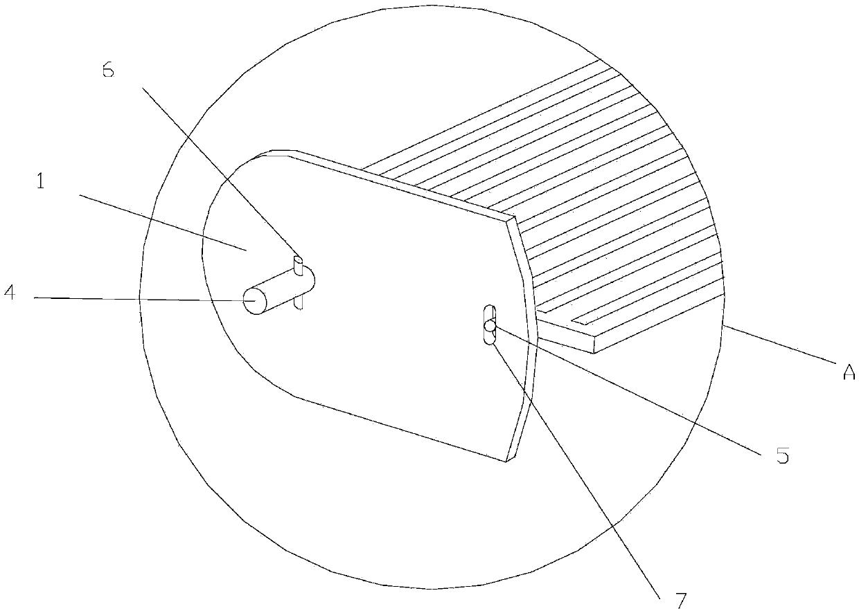
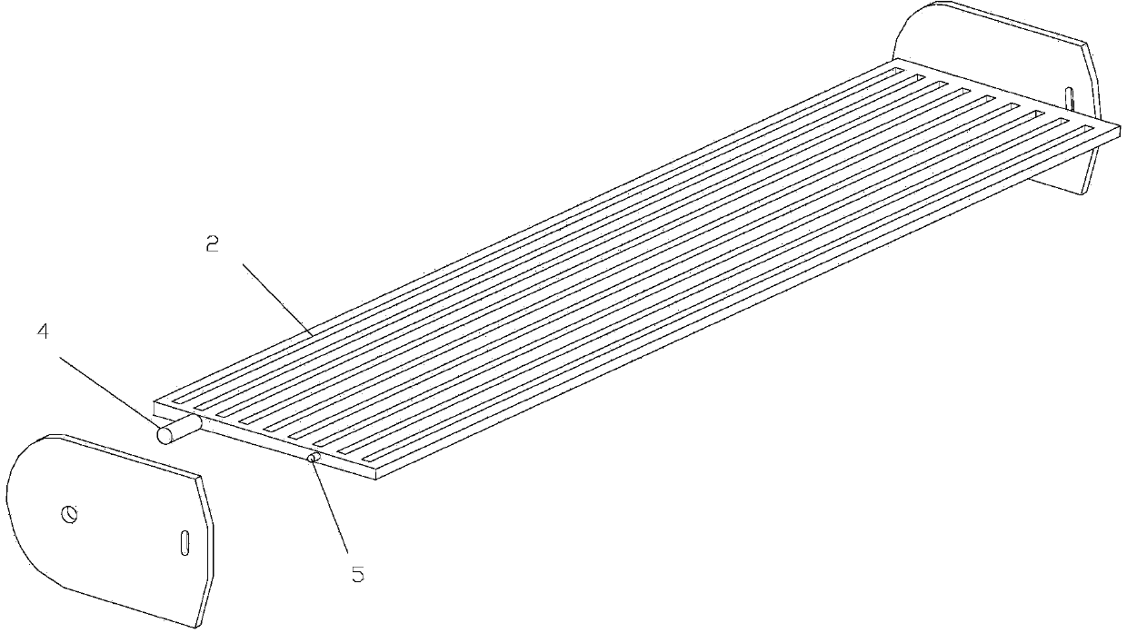
[0020] Such as figure 1 , 2 As shown in , 3, the conveying chain plate of a vegetable dehydration device described in this embodiment includes a side plate 1, the rear end of which is an arc-shaped end 3, and a conveying plate 2 is arranged between two side plates 1, The two ends of described conveying plate 2, rear portion is provided with chain connecting rib 4, and front end is provided with clamping rib 5, and described side plate 1 is provided with arc groove 7, and described chain connecting rib 4 passes through side plate 1 and A limit pin 6 is provided on the exposed section, and the clamping rib 5 is movably arranged in the arc-shaped groove 7 ; a ventilation slot 8 is provided on the conveying plate 2 . Among them; the connecting rib 4 and the clamping rib 5 can be welded on the conveying plate 2 .

[0021] The conveyor chain plate of the vegetable dehydration device described in this embodiment is provided with a ventilation slot 8 on the conveyor plate 2. The ve...

Embodiment 2

[0025] Such as Figure 4 As shown, the conveying chain plate of the vegetable dehydrating device described in this embodiment is different from Embodiment 1 in that: the conveying plate 2 is formed by connecting two wave plates 9 up and down with an intermediate plate 10, and the intermediate plate 10 is Gaps 11 are provided at equal intervals, and the wave plate 9 is formed by alternately arranging plane sections 91 and arcuate sections 92. The holes 12 , the ventilation slots 8 and the ventilation holes 12 communicate with the gap 11 on the middle plate 10 .

[0026] In this embodiment, the middle plate 10 can be a hard plastic plate, and the corrugated plate 9 can be a sanitary stainless steel plate or a hard plastic plate. Of course, the material can be used, and is not limited to the method disclosed in this embodiment.

[0027] Since the wave plate 9 is provided, the wave plate 9 has a protruding arc surface section 92, so that the vegetables are placed on the conveying...


PUM


Abstract

The invention discloses a conveying chain plate of a vegetable dehydrating device. The conveying chain plate comprises side plates, wherein the rear ends of the side plates are arc-shaped ends, and a conveying plate is arranged between the two side plates; the conveying chain plate is characterized in that for two ends of the conveying plate, the rear part of the conveying plate is provided with a chain connecting rib, the front end of the conveying plate is provided with a clamping rib, the side plates are provided with arc-shaped grooves, the chain connecting rib penetrates through the side plates and is provided with a limiting pin on an exposed section, and the clamping rib is movably arranged in the arc-shaped grooves; the conveying plate is provided with ventilating seams. According to the conveying chain plate of the vegetable dehydrating device, disclosed by the invention, the conveying plate is provided with the ventilating seams, the whole ventilating seam is not easily and compactly pressed, and the ventilating effect of the ventilating seams is superior to the ventilating effect of ventilating holes; in addition, during a conveying process of the conveying chain plate, certain deflection can be formed by the conveying plate, water carried by vegetables on the conveying plate can be more easily discharged due to the existence of an inclination degree, the downward deflection speed of the conveying plate is quicker when the vegetables are conveyed to a blanking opening, and the blanking efficiency is increased.

Description

[0001] technical field [0002] The invention relates to a combined heating vegetable dehydration device, in particular to a conveying chain plate of the vegetable dehydration device. Background technique [0003] Vegetable dryers are widely used in agriculture. Chinese patent ZL201110231890.3 discloses a combined heating vegetable dehydration device. Shandong University of Technology has applied for a number of invention patents for vegetable dryers. [0004] The combined heating vegetable dehydration device is composed of multi-layer conveyor belts. The conveyor belts are connected up and down through the discharge port. The basic unit of each conveyor belt is the conveyor chain plate. When conveying, the upper and lower sides of the conveyor chain plate will bear Delivery tasks. In the vegetable dryer, the vegetables are dried by the combination of hot air and infrared drying, so it is called combined type. [0005] When drying, the conveying chain plate is supported on...

Claims


Application Information

Patent Timeline
Patent Type & Authority Applications(China)
IPC IPC(8): F26B25/00A23N12/08
Inventor 罗静
Owner 罗静
Why Eureka
Try Eureka