
Mini-type multi-band frequency mobile phone antenna

A mobile phone antenna, multi-band technology, applied in the directions of the antenna, the antenna grounding device, the antenna support/installation device, etc., can solve the problems of reducing the wireless communication efficiency, increasing the difficulty of designing the antenna, weakening the receiving effect, etc., and achieving a simple structure, The effect of easy processing and easy adjustment

Active Publication Date: 2014-07-30
杭州微萤科技有限公司
View PDF4 Cites 10 Cited by
  • Summary
  • Abstract
  • Description
  • Claims
  • Application Information

AI Technical Summary

Problems solved by technology

With the increasing popularity of mobile phones, mobile phones have transformed from pure communication products to consumer electronics products due to the increase in functions. The motivation of many consumers to buy mobile phones is mainly attracted by their functions and designs. , may cause changes or reduce the performance of wireless communication, so it increases the difficulty of designing antennas
[0004]The ever-shrinking mobile phone antenna size means that the height and space of the antenna are compressed, and an efficient antenna must have sufficient height and space to expand the frequency band and efficiency. Although the design trend of the antenna is getting smaller and smaller, the size of the antenna itself still has its physical limitations. If the volume of the antenna is below the standard point, as the volume gradually shrinks, its reception effect It will also become weaker and weaker. Therefore, the miniaturization and multi-frequency design of the antenna is a hot and difficult point in the research of mobile phone antennas today.

Method used


Image

  • Mini-type multi-band frequency mobile phone antenna
  • Mini-type multi-band frequency mobile phone antenna
  • Mini-type multi-band frequency mobile phone antenna

Examples


Embodiment

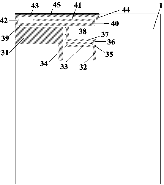
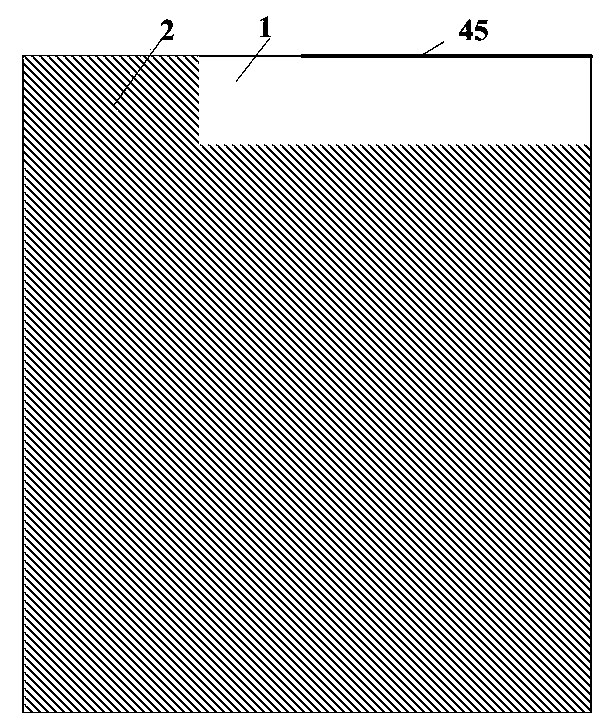
[0020] A miniaturized multi-band mobile phone antenna, such as figure 1 The radiation metal sheet group 3 includes an inverted L-shaped first metal sheet 31, a second metal sheet 32 ​​connected in sequence, a third metal sheet 33, a fourth metal sheet 34, a fifth metal sheet 35, and a sixth metal sheet 36 , the seventh metal sheet 37, the eighth metal sheet 38, the ninth metal sheet 39, the twelfth metal sheet 42, the thirteenth metal sheet 43, the fourteenth metal sheet 44, the fifteenth upright metal sheet 45, and along The second connected ninth metal sheet 39, the tenth metal sheet 40, and the eleventh metal sheet 41; the second metal sheet 32 ​​and the third metal sheet 33 form an inverted L shape, which is in phase with the first radiation metal sheet 31. Parallel, the second metal sheet 32, the fourth metal sheet 34, the sixth metal sheet 36, the eighth metal sheet 38, the tenth metal sheet 40, the twelfth metal sheet 42, and the fourteenth metal sheet 44 are parallel ...


PUM

PropertyMeasurementUnit
Heightaaaaaaaaaa

Abstract

The invention discloses a mini-type multi-band frequency mobile phone antenna and provides a planar monopole mobile phone antenna which is small in size, easy to manufacture, low in manufacturing cost and capable of meeting the multi-frequency requirement and meeting the requirement of the frequency bands of GSM850 / 900 / 1800 / 1900, UMTS and LTE2300 / 2500 at the same time. The antenna comprises a dielectric plate, an earth plate and a radiation metal sheet set, wherein the radiation metal sheet set is directly printed on the upper surface of the dielectric plate; an inverted-L-shaped radiation metal sheet directly carries out feed, one directly grounded bent radiation metal sheet is divided into two branches after being folded by several times, the multiple frequency bands can be covered with coupling between the directly fed inverted-L-shaped radiation metal sheet and the grounded radiation metal sheet set, the large bandwidth is achieved, the miniaturization and multiple frequencies of existing mobile phone antennas are achieved, and lumped elements and special substrate materials do not need to be loaded. The mini-type multi-band frequency mobile phone antenna is applicable to 2G / 3G / 4G mobile phones.

Description

technical field [0001] The invention belongs to the technical field of antennas, and in particular relates to a miniaturized multi-band mobile phone antenna. Background technique [0002] The radio frequency signal power output by the radio transmitter is sent to the transmitting antenna through the feeder, and radiated by the antenna in the form of electromagnetic waves. After the electromagnetic wave reaches the receiving point, the receiving antenna receives the radiated electromagnetic wave and sends it to the radio receiver through the feeder. It can be seen that the antenna can be regarded as a sensor that realizes the mutual conversion between radio frequency signals and electromagnetic waves, and is an important radio device for transmitting and receiving electromagnetic waves. Without an antenna, there is no wireless communication. [0003] In recent years, the mobile communication terminal equipment—the mobile phone has become the fastest-growing communication prod...

Claims


Application Information

Patent Timeline
IPC IPC(8): H01Q1/24H01Q1/36H01Q5/01H01Q1/48H01Q1/50H01Q5/10
Inventor 周浩淼梁艳武
Owner 杭州微萤科技有限公司
Learn More