System and method for adjusting output currents in power source transformation system

A technology for converting system and current, which is applied in the direction of converting AC power input to DC power output, DC power input converting to DC power output, and output power conversion devices, etc.

Active Publication Date: 2014-07-30
GUANGZHOU ON BRIGHT ELECTRONICS
View PDF2 Cites 15 Cited by
  • Summary
  • Abstract
  • Description
  • Claims
  • Application Information

AI Technical Summary

Problems solved by technology

But the conventional power conversion system 100 has some disadvantages

Method used


Image

  • System and method for adjusting output currents in power source transformation system
  • System and method for adjusting output currents in power source transformation system
  • System and method for adjusting output currents in power source transformation system

Examples


Embodiment Construction

[0023] Certain embodiments of the invention involve integrated circuits. More specifically, some embodiments of the present invention provide systems and methods for output current regulation. For example only, certain embodiments of the present invention have been applied to power conversion systems. However, it should be recognized that the present invention has a broader scope of application.

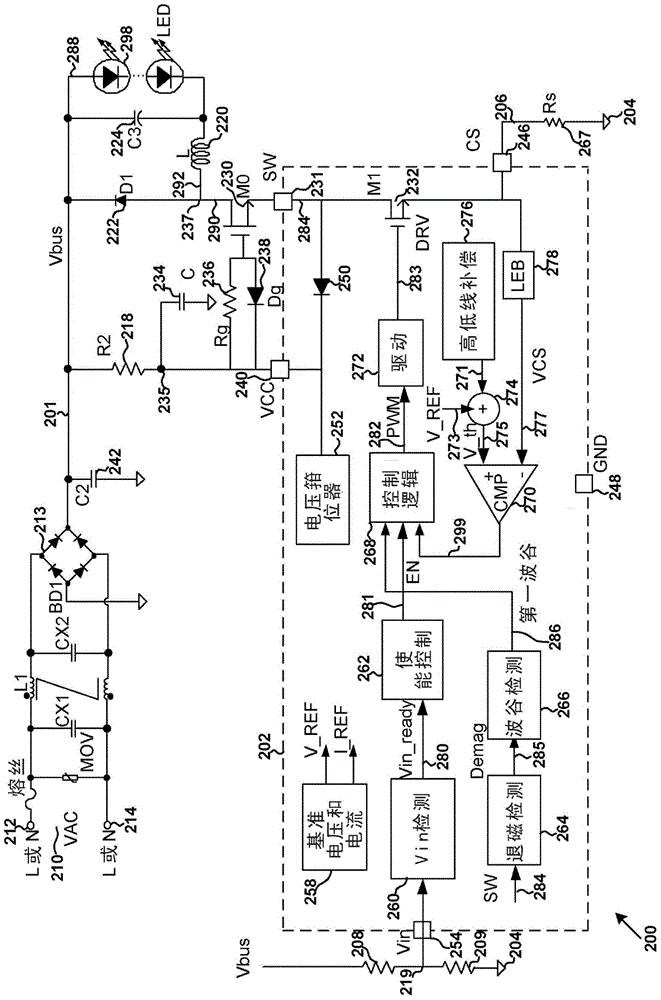
[0024] figure 2 It is a simplified diagram showing a power conversion system according to an embodiment of the present invention. The figure is only an example, which should not unduly limit the scope of the claims. Those of ordinary skill in the art will recognize many changes, substitutions, and modifications.

[0025] The system 200 includes a system controller 202, resistors 208, 209, 218, 236, and 267, a full-wave rectifier bridge 213, capacitors 224, 234, and 242, a switch 230, an inductor 220, diodes 222 and 238, and multiple LEDs 298. The system controller 202 includes a swit...


PUM


Abstract

The invention provides a system and method for adjusting output currents in a power source transformation system. A system controller comprises a detection assembly, a control logic assembly and a drive assembly. The detection assembly is used for receiving input voltage related to a diode connected to an inductor, making a response when the input voltage is larger than a preset threshold value and outputting a first signal through a first logic level. The control logic assembly is used for receiving the first signal, processing information related to the first signal, making a response when the first signal is in the first logic level and outputting a modulation signal related to the modulation frequency. The drive assembly is used for receiving the modulation signal and outputting a drive signal to modulate the frequent to switch on or switch off a first switch.

Description

Technical field [0001] Certain embodiments of the invention involve integrated circuits. More specifically, some embodiments of the present invention provide systems and methods for output current regulation. For example only, some embodiments of the present invention have been applied to power conversion systems. However, it should be recognized that the present invention has a broader scope of application. Background technique [0002] figure 1 It is a simplified diagram of a conventional buck power conversion system with primary-side sensing and regulation. The system 100 includes a system controller 102, resistors 118, 164, and 192, capacitors 108, 142, and 124, a power switch 130, an inductor 120, a diode 122, and a plurality of LEDs 198. In addition, the system controller 102 includes terminals 140, 144, 146, 148, and 154. [0003] A mains alternating current (AC) input 110 (for example, VAC) is provided to the input terminals 112 and 114. For example, the system control...

Claims


Application Information

Patent Timeline
Patent Type & Authority Applications(China)
IPC IPC(8): H02M3/156H05B44/00
CPCH02M3/157H02M3/156H02M7/2176G05F1/00Y02B20/30H05B45/3725H05B45/00H02M3/1582H02M3/158H02M3/335
Inventor 方烈义
Owner GUANGZHOU ON BRIGHT ELECTRONICS
Why Eureka
Try Eureka