Amplifier circuit applied to low power consumption system

An amplifier circuit and low power consumption technology, which is applied in the field of amplifier circuits of low power consumption systems, can solve problems such as increasing system power consumption, and achieve the effect of increasing power consumption

Inactive Publication Date: 2014-07-30
CHINA KEY SYST & INTEGRATED CIRCUIT
5 Cites 1 Cited by

AI-Extracted Technical Summary

Problems solved by technology

The existing circuit structure of adding a source follower circuit after the ampl...

Abstract

The invention discloses an amplifier circuit applied to a low power consumption system. The amplifier circuit comprises CMOSs (Complementary Metal-Oxide-Semiconductor Transistors) M1, M2, M3 and M4, resistors R1, R2, R3 and R4, capacitors C1 and C2 and a current source IDC, wherein the source end of the M1 is respectively connected to the source end of the M2 and the upper end of the IDC, the R1 is connected between the drain end of the M1 and the source end of the M3, and the C1 is connected between the drain end of the M1 and the grid end of the M3; the R3 is connected between the grid end of the M3 and a power supply VDD, and the drain end of the R3 is connected with the power supply VDD; the R2 is connected between the drain end of the M2 and the source end of the M4, and the C2 is connected between the drain end of the M2 and the grid end of the M4; the R4 is connected between the grid end of the M4 and the power supply VDD, and the drain end of the M4 is connected with the power supply VDD. The amplifier circuit has the beneficial effects that amplification of an input signal is realized in a first-level amplifier, a function of driving a backward-stage circuit is provided, and the amplifier circuit is very suitable for being applied to the low power consumption system.

Application Domain

Amplifier modifications to raise efficiency

Technology Topic

Oxide semiconductorCurrent source +5

Image

  • Amplifier circuit applied to low power consumption system

Examples

  • Experimental program(1)

Example Embodiment

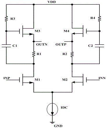
[0013] Such as figure 1 Shown is a schematic diagram of the circuit structure of the amplifier circuit of the present invention applied to a low power consumption system.
[0014] The CMOS transistor M1, the resistor R1 and the CMOS transistor M3 together form the amplification of the input forward signal INP. The input forward signal INP is input from the gate terminal of the CMOS transistor M1, and amplified by the CMOS transistor M1, and then the drain terminal of the CMOS transistor M1 Output, after the amplified signal is blocked by the capacitor C1, it is input from the gate terminal of the CMOS transistor M3, and then output from the source terminal of the CMOS transistor M3. Since the resistance seen from the source terminal of the CMOS transistor M3 is very small, only 1/ gm3, where gm3 is the transconductance of the CMOS transistor M3, so the CMOS transistor M3 has a good function of driving the subsequent circuit.
[0015] At the same time, the CMOS transistor M2, the resistor R2 and the CMOS transistor M4 together form the amplification of the input negative signal INN. The input negative signal INN is input from the gate terminal of the CMOS transistor M2 and amplified by the CMOS transistor M2. Drain output. After passing through the blocking capacitor C2, the amplified signal is input from the gate terminal of the CMOS transistor M4, and then output from the source terminal of the CMOS transistor M4. Since the resistance seen from the source terminal of the CMOS transistor M4 is very small, only 1/gm4, where gm4 is the transconductance of the CMOS transistor M4, so the CMOS transistor M4 has a good function of driving the subsequent circuit.
[0016] The ingeniousness of the circuit of the present invention is that the amplification function and the driving function do not affect each other in the first-level circuit. The clever use of resistors R1 and R2 effectively shields the effect of the low source input impedance of the CMOS transistor M3 and the source low input impedance of the CMOS transistor M4 on the gain of the amplifier, and the amplified signal passes through the capacitor C1 and the capacitor C2 respectively. Reaching the gate terminals of the CMOS transistor M3 and the CMOS transistor M4, follow the output via the source of the CMOS transistor M3 and the CMOS transistor M4, respectively. Furthermore, due to the low input impedance of the source terminals of the CMOS transistor M3 and the CMOS transistor M4, it can drive the subsequent circuit well.

PUM

no PUM

Description & Claims & Application Information

We can also present the details of the Description, Claims and Application information to help users get a comprehensive understanding of the technical details of the patent, such as background art, summary of invention, brief description of drawings, description of embodiments, and other original content. On the other hand, users can also determine the specific scope of protection of the technology through the list of claims; as well as understand the changes in the life cycle of the technology with the presentation of the patent timeline. Login to view more.

Similar technology patents

Wet flue gas desulfurization system and wet flue gas desulfurization method

PendingCN113797740AReduce desulfurization efficiencyincrease power consumption
Owner:FUJIAN LONGKING

VOCs waste gas treatment system and waste gas treatment method

PendingCN112283726Aincrease power consumptionextended stay
Owner:广东和炫环保智能科技有限公司

Integral bleeder circuit based on composite dielectric gate double-transistor photosensitive detector

PendingCN111540759Aincrease power consumptionReduce Op Amp Usage
Owner:NANJING UNIV

Classification and recommendation of technical efficacy words

  • increase power consumption

Low-voltage linear adjuster

ActiveCN101075143Aincrease chip areaincrease power consumption
Owner:ANYKA (GUANGZHOU) MICROELECTRONICS TECH CO LTD

An information processing method and electronic device

ActiveCN104410785Areduce power consumptionincrease power consumption
Owner:LENOVO (BEIJING) CO LTD

Method for reducing energy consumption of oxidizing reaction unit of phenol-acetone device

ActiveCN104478775AIncrease pipe resistanceincrease power consumption
Owner:SINOPEC SHANGHAI ENG +1

Integrated multiple waste heat coupling heating system

InactiveCN109631394Aincrease power consumptionreduce dosage
Owner:DALIAN NATIONALITIES UNIVERSITY

High-efficiency electronic igniter

ActiveCN102913947Aincrease power consumptionshort life
Owner:江帅辰
Why Eureka
Try Eureka