High-precision analog-to-digital converter and analog-to-digital conversion method

An analog-to-digital converter and analog-to-digital conversion technology, applied in the direction of analog-to-digital converters, etc., can solve the problem that the conversion accuracy of integral A/D converters is difficult to further improve, shorten the required time, avoid measurement errors, and solve Effect of Conversion Precision

Active Publication Date: 2014-07-30
石家庄数英仪器有限公司
View PDF3 Cites 12 Cited by
  • Summary
  • Abstract
  • Description
  • Claims
  • Application Information

AI Technical Summary

Problems solved by technology

[0007] One of the purposes of the present invention is to provide a high-precision analog-to-digital converter to s

Method used


Image

  • High-precision analog-to-digital converter and analog-to-digital conversion method
  • High-precision analog-to-digital converter and analog-to-digital conversion method
  • High-precision analog-to-digital converter and analog-to-digital conversion method

Examples


Embodiment 1

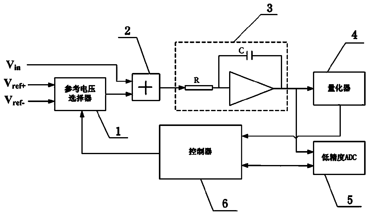
[0052] Embodiment 1, a high-precision analog-to-digital converter.

[0053] Such as figure 1 As shown, the high-precision analog-to-digital converter provided by the present invention includes a reference voltage selector 1 , a summer 2 , an integrator 3 , a quantizer 4 , a low-precision A / D converter 5 and a controller 6 .

[0054] The reference voltage selector 1 is respectively connected to the summer 2 and the controller 6, and under the control of the controller 6, it selectively outputs a positive reference voltage V ref+ signal or negative reference voltage V ref- Signal. Positive reference voltage V ref+ signal or negative reference voltage V ref- The signal is used to adjust the voltage signal output by the integrator 3, so that the voltage signal output by the integrator 3 will not reach a saturation state and maintain the charge balance of the integrating capacitor. The reference voltage signal output by the reference voltage selector 1 is sent to the summer 2 ...

Embodiment 2

[0084] Embodiment 2, a high-precision analog-to-digital conversion method.

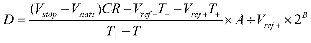
[0085] refer to figure 1 , the high-precision analog-to-digital conversion method provided by the present invention is specifically: the reference voltage selector 1 selectively outputs the positive reference voltage V under the control of the controller 6 ref+ signal or negative reference voltage V ref﹣ signal, the positive reference voltage V ref+ signal and negative reference voltage V ref﹣ The signal is a reference voltage signal capable of regulating the output of the integrator 3, the positive reference voltage V ref+ and negative reference voltage V ref﹣ Satisfy the relation: |V in(max) |ref± |in(max) |, V in(max) is the maximum value of the input voltage, the reason for selecting the value range of the positive and negative reference voltages can be referred to the description in Embodiment 1; the positive reference voltage V ref+ signal or negative reference voltage V ref﹣ signal and ...


PUM


Abstract

The invention provides a high-precision analog-to-digital converter and an analog-to-digital conversion method. The high-precision analog-to-digital converter comprises a reference voltage selector, a summator, an integrator, a quantizer, a low-precision analog-to-digital converter and a controller. According to the high-precision analog-to-digital converter, the reference voltage selector selectively outputs positive reference voltage signals or negative reference voltage signals, the positive reference voltage signals and the negative reference voltage signals are switched continuously, it can be guaranteed that voltage signals output by the integrator cannot be saturated, therefore, the integration time can be prolonged, and the conversion precision can be improved. The low-precision analog-to-digital converter is used for collecting voltage signals output by the integrator when measurement is started and ended, on one hand, the step that integration needs to be conducted on residual charges again when measurement is ended each time can be omitted, and the conversion speed is increased; on the other hand, the situation that the conversion precision is affected due to the fact that the initial voltage of the integrator is not zero can be avoided, and therefore the conversion precision is further improved.

Description

technical field [0001] The invention relates to an analog-to-digital converter, in particular to a high-precision analog-to-digital converter and an analog-to-digital conversion method. Background technique [0002] An analog-to-digital converter (A / D converter or ADC for short) refers to an electronic device that converts an analog quantity into a digital quantity. A common A / D converter collects analog voltage signals from a signal system, and converts the analog voltage signals into equivalent digital voltage signals after signal processing. The most important performance indicators of the A / D converter are conversion accuracy (referred to as precision) and conversion speed (referred to as speed). Accuracy indicates the relative error between the actual value of the analog voltage and its corresponding digital quantity, which can be expressed as "truth". In A / D converters, resolution and conversion error are usually used to describe the conversion accuracy. Resolution ...

Claims


Application Information

Patent Timeline
IPC IPC(8): H03M1/12
Inventor 邓志成蒋富雄田云温航宇
Owner 石家庄数英仪器有限公司
Why Eureka
Try Eureka