
Internal combustion engine and method for operating the internal combustion engine
A technology for internal combustion engines and motion, applied in the direction of machines/engines, mechanical equipment, engine components, etc., can solve problems such as failures, component throttle valves, turbocharger valve dirt, efficiency loss, etc.
- Summary
- Abstract
- Description
- Claims
- Application Information
AI Technical Summary
Problems solved by technology
Method used
Image

Examples
Embodiment Construction
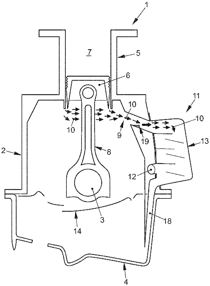
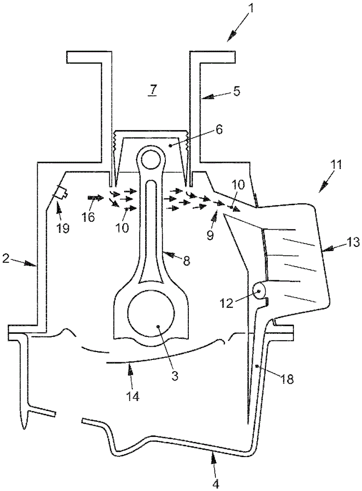
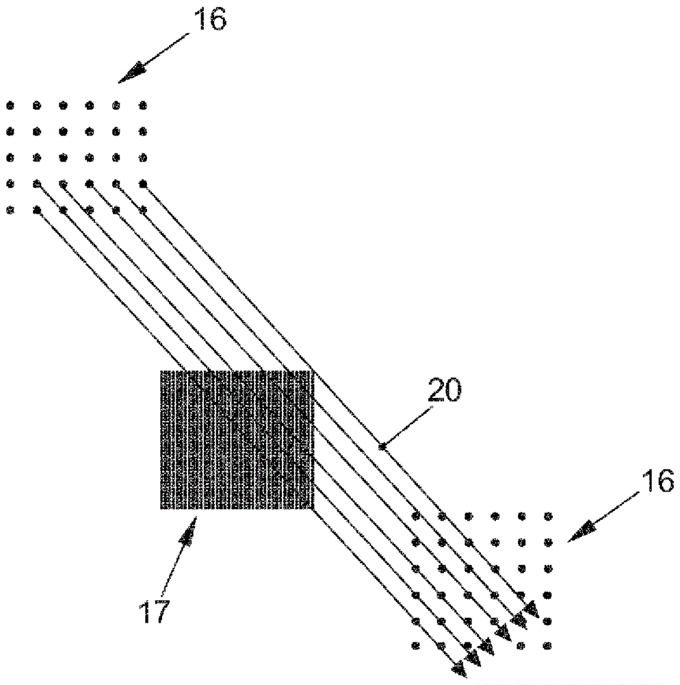
[0021] figure 1 , 2 and 3 show an internal combustion engine 1 with a crankcase 2 in which a crankshaft 3 is arranged movably about an axis of rotation not shown. In the configuration of the internal combustion engine 1 shown here, the crankcase 2 is delimited on one side by an oil sump 4 and on the other side by a cylinder 5 . The invention can also be used in other configurations of the internal combustion engine 1 , for example in V-engines or opposed-cylinder engines. A piston 6 is arranged in translational motion within the cylinder 5 . Piston 6 closes working chamber 7 of internal combustion engine 1 from crankcase 2 . Piston 6 is connected to crankshaft 3 via connecting rod 8 , also called drive rod. The blow-by gas entering the crankcase 2 next to the piston 6 is indicated by small arrows as blow-by flow 10 . The blow-by flow 10 is conveyed via a gas recirculation device 11 to the fresh-gas side of the internal combustion engine 1 , not shown in detail. Only the c...
PUM
 Abstract
Description
Claims
Application Information