
A fully automatic pipe cutting machine

A pipe cutting machine, fully automatic technology, applied in the direction of turning equipment, auxiliary devices, manufacturing tools, etc., can solve the problems that cannot meet the high precision of production, the processing technology is difficult to complete, and cannot be directly cut and used, so as to achieve convenient processing parameters , Saving process time and high production efficiency

Active Publication Date: 2017-04-05
YANCHENG SHUANGJIA ELECTRIC
View PDF6 Cites 0 Cited by
  • Summary
  • Abstract
  • Description
  • Claims
  • Application Information

AI Technical Summary

Problems solved by technology

When feeding manually, the operator visually measures the length with his eyes. Due to the different viewing angles, the determined error is at least about 0.30mm, which cannot meet the requirements of high precision production.
Moreover, the straightness of the incision is low, and most of them need secondary processing to meet the use requirements. The work generally requires the cooperation of two workers to complete
Moreover, the traditional cutting process has low efficiency, high labor intensity and low safety factor
The pipes purchased directly from the market have rust on the outside, and generally cannot be cut and used directly. After cutting, they need to be derusted and deburred. These processing techniques are difficult to complete on one machine.
The technicians of scientific research units and enterprises are constantly exploring and researching, hoping to develop a fully automatic pipe cutting machine with superior performance to overcome the defects of the existing technology. There are technical challenges that have not yet been overcome

Method used


Image

  • A fully automatic pipe cutting machine
  • A fully automatic pipe cutting machine

Examples


Embodiment Construction

[0014] The present invention is further described below in conjunction with accompanying drawing and embodiment:

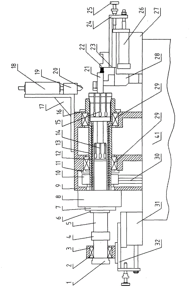
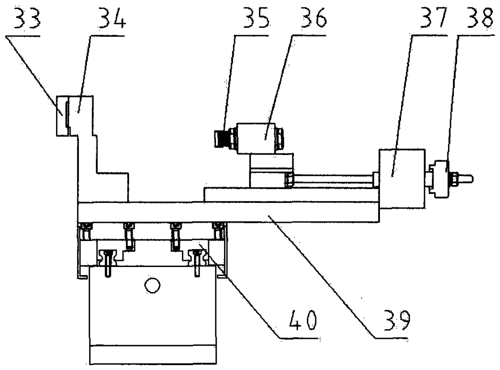
[0015] A full-automatic pipe cutting machine, including a hydraulic control part, an air circuit control part, and a PLC control part; There is a pair of bearing housings, the main shaft 13 is statically fitted in the center hole of the bearing II29 fitted in the pair of bearing housings, the bearing II29 is divided into a front bearing and a rear bearing, the front bearing is provided with a front bearing pressure plate, and the rear bearing is provided with a rear bearing. The end bearing pressure plate, the main shaft 13 is fixed with a driven wheel 10, the driven wheel 10 is connected with the driving wheel equipped with the motor with a belt 30, the oil pump assembly and the motor are installed in the frame seat 41, and the inner hole of the main shaft 13 is dynamically matched with a chuck. Tighten the tube 12, the chuck tightens the left peripheral step sha...


PUM

PropertyMeasurementUnit
thicknessaaaaaaaaaa

Abstract

The invention relates to the field of pipe cutting equipment, in particular to a full-automatic pipe cutter. The full-automatic pipe cutter is characterized in that a spindle box, a cutting tool rest portion and an external turning tool rest portion are fitted on a rack base, the spindle box is provided with a pair of bearing blocks therein, a spindle is fixedly fitted in a center hole of a bearing II fitted in the bearing blocks, the external turning tool rest portion and the cutting tool rest portion are arranged on the right side of the spindle box, a left connector of a feed chuck is connected to a right hole of a feed chuck push pipe, an outer chuck is arranged on the right side of the feed chuck, the right portion of the outer chuck is as tapered as a tapered portion of the inner wall of the spindle, the bottom of a push pipe bearing block is fixed on a feed carriage, and a feed carriage base is fixed on the rack base. The full-automatic pipe cutter is designed by combining the principle of pneumatics, the principle of hydraulics and the principle of PLC control; the full-automatic pipe cutter is applicable to external turning, double-end chamfering and automatic pipe cutting length measurement; operating efficiency is improved, labor intensity is decreased, machining precision is high, yield is high, and utilization rate of raw materials is high.

Description

technical field [0001] The invention relates to the field of pipe cutting equipment, in particular to a fully automatic pipe cutting machine. Background technique [0002] Since the reform and opening up, the national economy has grown rapidly, "scientific and technological innovation, independent innovation" has become the mainstream of domestic industrial development, and my country's industry is gradually developing in the direction of intensive, energy-saving, emission-reducing, and low-carbon. Pipe cutters are widely used in industrial production as pipe cutting equipment. At present, the traditional method of cutting pipe materials mainly relies on machine tools or grinding wheel cutting machines, adopts manual feeding, and determines the cutting length of pipe fittings with a square ruler. During manual feeding, the operator visually measures the length with his eyes. Due to the different viewing angles, the determined error is at least about 0.30 mm, which cannot me...

Claims


Application Information

Patent Timeline
Patent Type & Authority Patents(China)
IPC IPC(8): B23B5/08B23B5/16B23B15/00B23B25/06
CPCB23B5/08B23B5/167B23B25/06B23Q7/043
Inventor 王新华
Owner YANCHENG SHUANGJIA ELECTRIC
Learn More