Automatic welding method for hydraulic hard tube assembly

An automatic welding and hard pipe technology, applied in welding equipment, welding equipment, welding accessories, etc., can solve the problems of hard pipe assembly, complex shape, and reduced production efficiency, and achieve rapid docking and positioning, beautiful shape, and welding Seam penetration effect

Active Publication Date: 2014-08-06
CHANGZHI QINGHUA MACHINERY FACTORY +1
View PDF6 Cites 5 Cited by
  • Summary
  • Abstract
  • Description
  • Claims
  • Application Information

AI Technical Summary

Problems solved by technology

[0007] The shortcomings of closed self-fluxing TIG all-position welding are: a. Welding wall thickness ≤ 2mm, not covering the welding wall thickness of hard pipe assembly ≤ 4.5mm; b. The inner and outer diameters of the welds are required to be equal, while the inner and outer diameters of the tube and the spherical joint in the hard pipe assembly are basically unequal, so the scope of application of this method is very small; c. In the case that the inner and outer diameters of the conduit and the spherical joint of the hard pipe assembly are basically unequal, it is difficult to quickly ensure the butt joint gap ≤ 0.2mm and the butt misalignment ≤ 0.2mm, which will inevitably reduce production efficiency; d. The clamping straight section is generally ≥ 21mm, which cannot be welded in the case of a hard tube assembly with a sharp bend but no straight section, and a clamping straight section < 21mm; e. The welding groove is flat, while the welding groove of the hard pipe assembly is V-shaped, that is, to adapt to this welding method, it is necessary to carry out flat processing on the conduit and the spherical joint
[0008] The disadvantages of open filling wire TIG all-position welding are: a. TIG welding is used for welding, which can be welded with or without filler wire
That is, when the welding wall thickness is greater than 3.5mm, both the conduit and the joint need to be grooved in a J shape. However, due to factors such as long size, complex shape, and short straight line for clamping, it is difficult to make a J-shaped groove. Into difficult to use this method of welding; b. The inner and outer diameters of the welds are required to be equal, while the inner and outer diameters of the tube and the spherical joint in the hard pipe assembly are basically unequal, so the scope of application of this method is very small; c. In the hard tube assembly, when the inner and outer diameters of the tube and the spherical joint are basically unequal, it is difficult to quickly ensure the butt joint gap ≤ 0.2mm and the butt misalignment ≤ 0.2mm, which will inevitably reduce production efficiency; d. The clamping straight section is generally ≥132mm, which cannot be welded for the hard pipe assembly where the conduit has a sharp bend but no straight section, and the clamping straight section is <132mm; e. When the welding wall thickness is less than or equal to 3.5mm, the welding groove is flat, while the welding groove of the hard pipe assembly is V-shaped, that is, to adapt to this welding method, it is necessary to carry out flat processing on the conduit and the spherical joint
[0009] The disadvantages of open wire filling TIG horizontal welding are: a. The inner and outer diameters of the welds are required to be equal, while the inner and outer diameters of the conduit and the ball joint in the hard pipe assembly are basically unequal, so the scope of application of this method is very small; b. In the case of tubes and ball joints in the hard tube assembly with basically unequal inner and outer diameters, it is difficult to quickly ensure that the butt joint gap is ≤0.2mm and the wrong side of the butt joint is ≤0.2mm, which will inevitably reduce production efficiency; c. The clamping straight section is generally ≥90mm, which cannot be welded for the hard pipe assembly where the conduit has a sharp bend but no straight section, and the clamping straight section is less than 90mm; d. The welding groove is flat, while the welding groove of the hard pipe assembly is V-shaped, that is, to adapt to this welding method, it is necessary to carry out flat processing on the conduit and the spherical joint
[0010] To sum up, no matter what kind of automatic welding technology is difficult to be widely used in the welding process of hydraulic hard pipe assembly, the welding rate of automatic welding is low, and the welding quality is not stable enough

Method used


Image

  • Automatic welding method for hydraulic hard tube assembly
  • Automatic welding method for hydraulic hard tube assembly
  • Automatic welding method for hydraulic hard tube assembly

Examples


Embodiment Construction

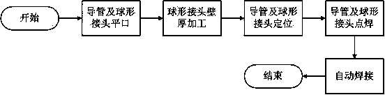
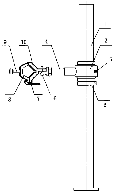
[0032] Such as figure 1 , figure 2As shown, a hydraulic hard pipe assembly automatic welding method is carried out according to the following steps:

[0033] The first step is to process the welding groove of the conduit in the hydraulic hard pipe assembly and the welding groove of the spherical joint into flat grooves;

[0034] In the second step, the conduit of the hydraulic hard pipe assembly after the first step is assembled with the spherical joint, and the assembly of the spherical joint is processed to be equal to the inner diameter and outer diameter of the conduit, the length of the inner diameter is 5-10mm, and the Diameter length ≥ 21mm, fillet transition at the step, fillet radius R ≥ 3mm;

[0035] The third step is to position the conduit and the ball joint of the hydraulic hard pipe assembly after the second step, use the same outer diameter of the conduit and the ball joint for radial positioning, and use the flat blunt edge of the conduit and the ball joint ...


PUM


Abstract

The invention belongs to the technical field of welding and relates to a welding technology for a hydraulic hard tube, in particular to an automatic welding method for a hydraulic hard tube assembly. By the adoption of the automatic welding method for the hydraulic hard tube assembly, the welding ratio of automatic welding is high, and the welding quality is stable when the hydraulic hard tube assembly is welded. According to the technical scheme, the automatic welding method for the hydraulic hard tube assembly comprises the following steps that firstly, a welding groove of a guide tube and a welding groove of a spherical joint in the hydraulic hard tube assembly are machined to be plain ends; secondly, the guide tube and the spherical joint of the hydraulic hard tube assembly generated after the first step are grouped, and the inner diameter and the outer diameter of the position, where the spherical joint and the guide tube are grouped, of the spherical joint are machined to be equal to the inner diameter and the outer diameter of the guide tube respectively; thirdly, the guide tube and the spherical joint of the hydraulic hard tube assembly generated after the second step are in butt joint with each other and located; fourthly, spot welding is conducted on the guide tube and the spherical joint of the hydraulic hard tube assembly generated after the third step; fifthly, automatic welding is conducted on the guide tube and the spherical joint of the hydraulic hard tube assembly generated after the fourth step.

Description

technical field [0001] An automatic welding method for a hydraulic hard pipe assembly belongs to the field of welding technology, in particular to a welding technology involving hydraulic hard pipes. Background technique [0002] The main implementation standard of the hydraulic hard pipe assembly is Q / Dc322-2008 "37° hard pipe assembly commonly used in hydraulic systems", and the main parameters are shown in Table 1. [0003] [0004] It can be seen from Table 1 that the material and welding groove of the conduit and ball joint are the same, but the specifications and wall thickness are different. Due to the implementation of different specifications and standards for catheters and spherical joints, the structural dimensions of the inner and outer diameters of the two are inconsistent, and they cannot be combined in the state of equal inner and outer diameters. There are three main manifestations: a. The inner diameter and outer diameter of the catheter and the ball hea...

Claims


Application Information

Patent Timeline
Patent Type & Authority Applications(China)
IPC IPC(8): B23K9/00B23K9/167B23K9/235B23K9/32B23K37/053
CPCB23K9/167B23K9/235B23K37/0533B23K2101/06
Inventor 王威张明新艾敏贾艳萍仇小红才冬涛弓伟
Owner CHANGZHI QINGHUA MACHINERY FACTORY
Why Eureka
Try Eureka