Polishing machine

A polishing machine and frame technology, which is applied in the polishing machine field, can solve the problems of unstable fixation, offset worktable, and low adjustment precision, and achieve the effects of wide adjustment range, precise precision and long force arm.

Active Publication Date: 2014-08-06
陈美青
View PDF7 Cites 3 Cited by
  • Summary
  • Abstract
  • Description
  • Claims
  • Application Information

AI Technical Summary

Problems solved by technology

Although the workbench of this polishing machine can be adjusted, it can be used to process workpieces of various shapes, but because the workbench is adjusted by the spring and the positioning part after the angle is adjusted, that is, the positioning part is pressed against the workbench by the elastic force of the spring. On the side, it is fixed by the friction between the positioning piece and the worktable, the worktable and the frame, and the polishing machine has a certain vibration during use, and at the same time, it needs to apply force to press the workpiece on the polishing surface The above-mentioned fixing method is easy to cause the workbench to shift and the fixation is not firm. At the same time, the above-mentioned workbench is realized by turning the handle when adjusting the angle, that is, the rotation angle of the handle is the adjustment angle of the workbench, and its adjustment accuracy lower

Method used


Image

  • Polishing machine
  • Polishing machine
  • Polishing machine

Examples


Embodiment 1

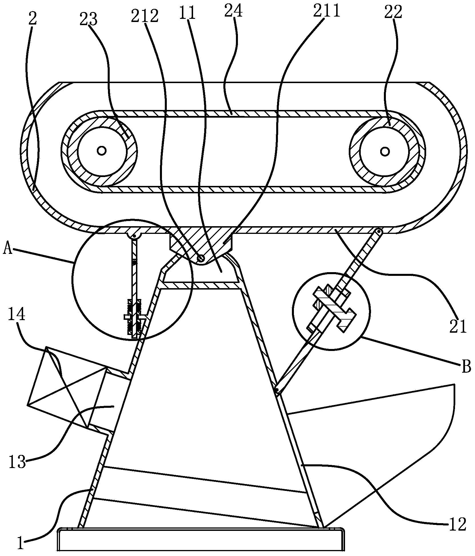
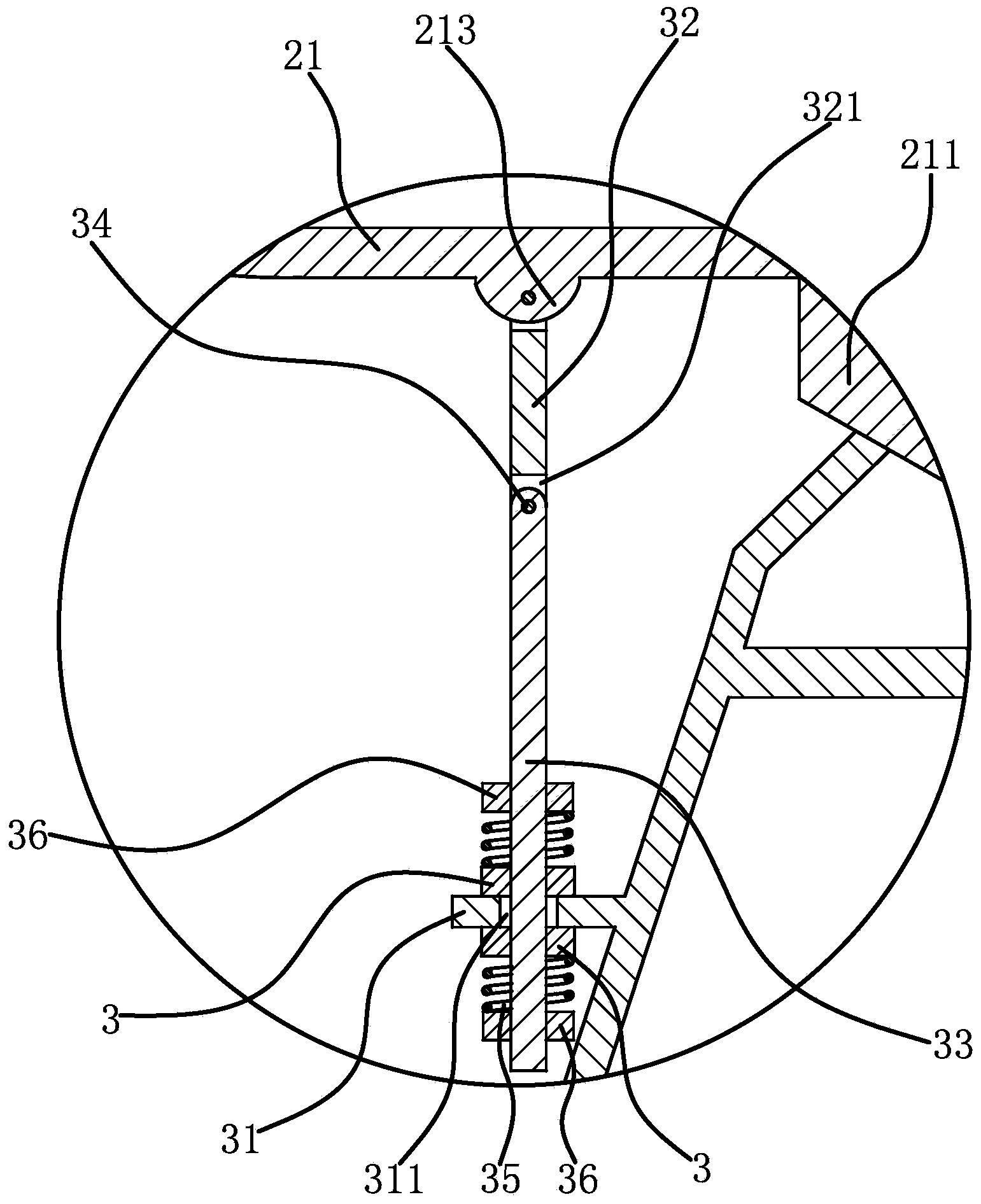
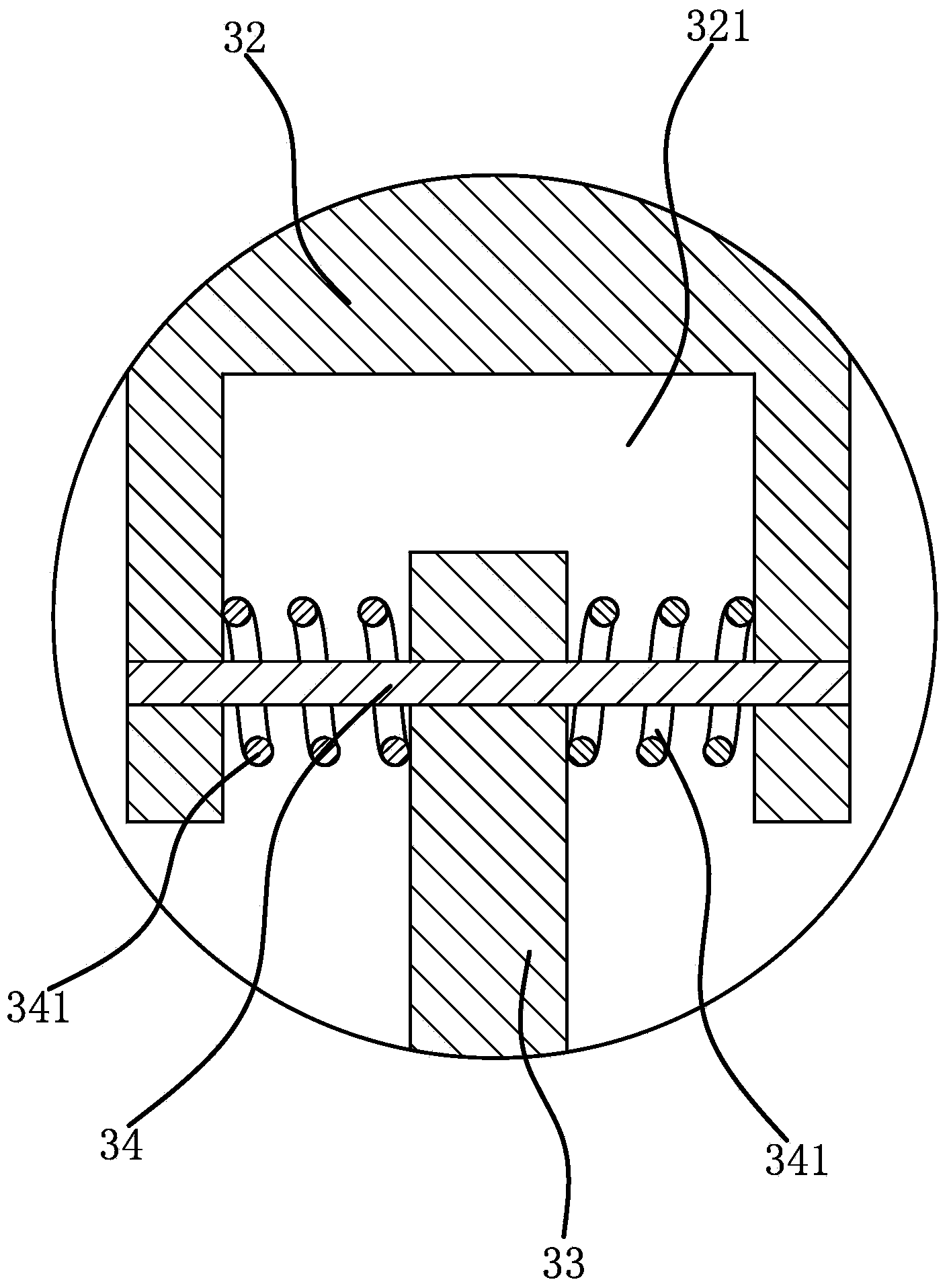
[0031] Such as figure 1 As shown, a polishing machine includes a frame 1 and a workbench 2. The workbench 2 is in the shape of a strip. The lower part of the workbench 2 is connected to the top of the frame 1 through a connecting shaft 212. There is a driving wheel 22 and a driven wheel 23, the driving wheel 22 and the driven wheel 23 are respectively rotatably connected to the two ends of the workbench 2, and the polishing belt 24 is set on the driving wheel 22 and the driven wheel 23, and the polishing belt 24 is set After driving wheel 22 and driven wheel 23, it can run along the length direction of workbench 2. The upper side and two arcuate surfaces of polishing abrasive belt 24 are polishing work points, and frame 1 and workbench 2 lower ends also pass through A connecting assembly with a screw 33 is connected, and the lower end of the screw 33 is slidingly connected to the frame 1 , and a positioning nut 3 is sleeved on the screw 33 , and the positioning nut 3 can axial...

Embodiment 2

[0036] The structure of the polishing machine is basically the same as that of Embodiment 1, the difference is that Figure 5 , Figure 6 , Figure 7 As shown, a strip-shaped adjusting plate 4 is also provided between the two connecting plates 11, and an annular connecting groove 111 is provided on the opposite sides of the two connecting plates 11, and the connecting groove 111 is coaxially arranged with the connecting hole, and the adjusting plate 4 The two relatively long edges of the upper side are vertically fixed with a support plate 41, and a through hole 411 is opened on the support plate 41. The outer surface of the support plate 41 surrounds the through hole 411 and has an annular convex edge 412, which is slidably connected to the connection In the slot 111 , the connecting shaft 212 passes through the through hole 411 , and an adjustment mechanism 5 capable of adjusting the angle of the table surface of the workbench 2 is provided between the adjustment plate 4 an...


PUM


Abstract

The invention provides a polishing machine, and belongs to the technical field of machining. The polishing machine solves the problem that the angle adjusting precision of a workbench of an existing polishing machine is low. The polishing machine comprises a machine frame and a workbench, wherein the lower portion of the workbench is rotationally connected to the upper portion of the machine frame through a connection shaft, a driving wheel and a driven wheel are rotationally connected with the workbench, and the driving wheel and the driven wheel are sleeved with a polishing abrasive belt; the lower end of the machine frame is further connected with the lower end of the workbench through a connection assembly provided with a screw, the lower end of the screw is connected to the machine frame in a sliding mode, and the screw is sleeved with a positioning nut capable of axially positioning the screw. According to the polishing machine, the angle of the workbench can be adjusted, the adjustment precision is high, and the workbench is fixed more firmly after adjustment is completed.

Description

technical field [0001] The invention belongs to the technical field of mechanical processing and relates to a polishing machine. Background technique [0002] Polishing machine is one of the indispensable mechanical equipment in the field of mechanical processing. It is more commonly used. After the workpiece is processed, the surface is polished and polished to remove the damaged layer and rough layer on the surface of the workpiece. There are various types of polishing machines, and the use is more common. The polishing machine generally includes a frame, a workbench, a driving wheel, a driven wheel, and a polishing belt set on the driving wheel and the driven wheel. The driving wheel is driven by the power device to rotate, and then the polishing belt is driven to apply force Press firmly on the surface of the polishing belt for polishing. [0003] Such as the Chinese invention patent application (application number: 200810059165.0) discloses an improved polishing machin...

Claims


Application Information

Patent Timeline
IPC IPC(8): B24B21/00B24B21/18
CPCB24B21/00B24B21/18
Inventor 陈美青
Owner 陈美青
Why Eureka
Try Eureka