
Commercial vehicle cab roof structure

A technology for cabs and commercial vehicles, applied in the field of truck cabs, can solve the problems of low production cost, difficult welding, high production cost, high welding difficulty, etc., to improve the proximity of welding tongs, low production cost, and low welding difficulty. Effect

Inactive Publication Date: 2014-08-06
DONGFENG COMML VEHICLE CO LTD
View PDF9 Cites 10 Cited by
  • Summary
  • Abstract
  • Description
  • Claims
  • Application Information

AI Technical Summary

Problems solved by technology

[0006] The purpose of the present invention is to overcome the defects and problems of high production cost, high welding difficulty and easy rain leakage in the prior art, and provide a commercial vehicle driver with low production cost, low welding difficulty and no easy rain leakage. roof structure

Method used


Image

  • Commercial vehicle cab roof structure
  • Commercial vehicle cab roof structure

Examples


Embodiment 1

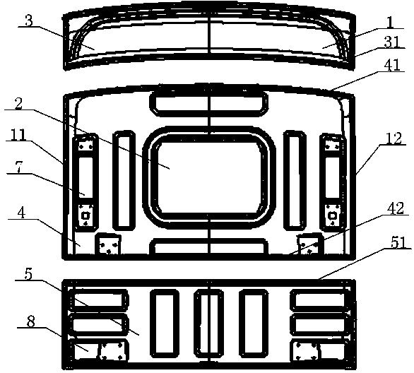
[0049] see figure 1 – figure 2 , a commercial vehicle cab roof structure, including a roof 1 and a sunroof 2, the roof 1 is an arc structure, the middle of the roof 1 is higher than its left side 11, right side 12, the roof 1 includes the front top cover 3, the middle top cover 4 and the rear top cover 5, the front top cover 3 is connected with the rear top cover 5 through the middle top cover 4, the rear top cover 5 is higher than the middle top cover 4, and the middle top cover 4 is higher A skylight 2 is opened in the middle of the front roof 3 and the middle roof 4;

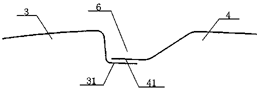
[0050] One end of the near-middle roof 4 on the described front roof 3 is provided with a front lap edge 31, and an end of the near front roof 3 on the middle roof 4 is provided with a middle upper lap edge 41, and the near rear top is provided on the middle roof 4. One end of the cover 5 is provided with a middle and lower lap edge 42, and one end of the near-middle top cover 4 on the back top cover 5 is ...


PUM


Abstract

A commercial vehicle cab roof structure comprises a front roof, a middle roof and a rear roof. The front roof, the middle roof and the rear roof are connected in sequence, the rear roof is higher than the middle roof, the middle roof is higher than the front roof, a skylight opening is formed in the middle of the middle roof, the front roof is connected with the middle roof through a front lap-joint edge and an upper middle lap-joint edge, the middle roof is connected with the rear roof through a lower middle lap-joint edge and a rear lap-joint edge, the front lap-joint edge and the upper middle lap-joint edge are connected to form a flow guide groove, the lower middle lap-joint edge and the rear lap-joint edge are connected to form a flow guide groove, a plurality of middle reinforcement ribs are arranged at the positions, close to the left side edge and the right side edge, of the middle roof, and a plurality of rear reinforcement ribs are arranged at the positions, close to the left side edge and the right side edge, of the rear roof. The commercial vehicle cab roof structure is low in production cost and low in welding difficulty, rain is not prone to being leaked, wind resistance is small, and energy consumption is low.

Description

technical field [0001] The invention belongs to the technical field of truck cabs, and in particular relates to a roof structure of a commercial vehicle cab, which is particularly suitable for reducing production costs and welding difficulty, and is not prone to rain leakage. Background technique [0002] The traditional truck cab roof is composed of one steel plate or two steel plates connected, and the two steel plates are usually welded at the ribs. Such top covers usually have the following deficiencies: [0003] 1. The size of the blank required for the top cover made of a steel plate is very large, difficult to purchase, and the cost is high. At the same time, the tonnage of the punching machine required to process the blank is very large, which increases the production cost again. In addition, when the top cover and the back wall are welded, due to the large size of the top cover, the welding tongs are not easy to get close to the welding edge, which increases the di...

Claims


Application Information

Patent Timeline
IPC IPC(8): B62D25/06B62D33/06B62D27/02
Inventor 张欣叶琳冯薇丽付尧马泽任伍星
Owner DONGFENG COMML VEHICLE CO LTD
Learn More