Large-current collector ring device of generator

A collector ring and high current technology, applied in the direction of electromechanical devices, electrical components, etc., can solve the problems of small number of conductive screws, poor current distribution uniformity, and small current carrying capacity, and achieve uniform current distribution, manufacturing difficulty and material cost. The effect of reducing and increasing the current carrying capacity

Active Publication Date: 2013-12-18
DONGFANG ELECTRIC MACHINERY
View PDF4 Cites 0 Cited by
  • Summary
  • Abstract
  • Description
  • Claims
  • Application Information

AI Technical Summary

Problems solved by technology

Each collector ring is connected to a conductive screw through a current sharing ring, the number of conductive screws is small, and the current sharing ring covers a 180° angle of the collector ring circumference, the current distribution uniformity is poor, and the current carrying capacity is small

Method used


Image

  • Large-current collector ring device of generator
  • Large-current collector ring device of generator
  • Large-current collector ring device of generator

Examples


Embodiment Construction

[0021] The present invention will be further described below in conjunction with accompanying drawing:

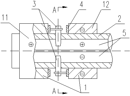
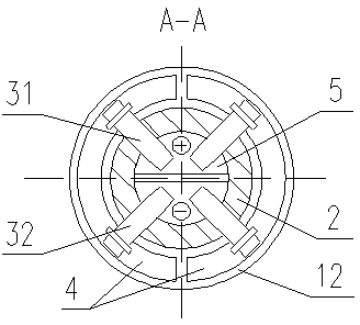
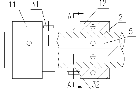
[0022] Generator high-current slip ring device, including slip ring (positive pole) 11, slip ring (negative pole) 12, and current sharing ring 4 arranged on the rotor, used to connect the conductive rod 5 and current sharing ring 4 in the rotor Conductive screw 3, each current sharing ring 4 is composed of 2 half-rings to form a whole ring, which is combined on the side of the collector ring 1, covering the 360° angle of the side of the collector ring 1, and each half-ring is correspondingly equipped with a conductive screw 3 , connected to the same pole of the conductive rod 5 in the rotor through the conductive screw 3, each current sharing ring 4 is connected to two conductive screws 3, and the four conductive screws 3 of the two collector rings 1 are symmetrically arranged on the center of the rotor on the same axial section.


PUM


Abstract

The invention provides a large-current collector ring device of a generator, which aims to solve the problems of the existing collector ring, such as less number of conductive screws, low current carrying capacity, long axial length, poor rotor operation stability, and large rotor blank dimension. The device comprises collector rings arranged on a rotor, a current sharing ring, and conductive screws for connecting the current sharing ring and a conductive rod in the rotor, wherein the collector rings are connected with the conductive screws through the current sharing ring; two conductive screws are arranged on each collector ring; and four conductive screws on two collector rings are arranged on the same axial section of the rotor in a central symmetric manner. The four conductive screws in central symmetric arrangement are completely symmetric in structure and weight so as to eliminate vibration due to asymmetric weight while rotating, the collector ring has large outer diameter and short length, and the collector ring device has short axial length, thereby shortening the rotor length, improving rotor operation stability, reducing rotor blank dimension, and lowering the manufacture difficulty and material cost.

Description

technical field [0001] The invention relates to the technical field of generators, and provides a high-current collector ring device for generators. Background technique [0002] The generator slip ring device is a current conduction device that leads the excitation current from the carbon brush holder (stationary part) to the generator rotor (rotating part). There are two technical solutions for the existing generator slip ring device: [0003] 1. The device consists of 2 collector rings and 4 conductive screws. Each collector ring is connected with 2 conductive screws, and the 2 sets of conductive screws are respectively located on the two axial sections of the generator rotor. The structure and weight are asymmetrical, and there is inherent imbalance. The axial length of the entire collector ring device is large. , the rotor running stability is low; the rotor blank size is long, the manufacturing difficulty and material cost are high; the conductive screw and the collec...

Claims


Application Information

Patent Timeline
Patent Type & Authority Patents(China)
IPC IPC(8): H02K13/00
Inventor 胡德剑王拯元令红兵潘峰
Owner DONGFANG ELECTRIC MACHINERY
Why Eureka
Try Eureka