
Adjustable brake handle with switch

An adjustable and switchable technology, applied to bicycle accessories, bicycle brakes, etc., can solve the problems of inaccurate adjustment, increased volume, and increased weight, and achieve the effects of saving raw materials, increasing the effective area, and reducing weight

Inactive Publication Date: 2014-08-06
张小红
View PDF1 Cites 4 Cited by
  • Summary
  • Abstract
  • Description
  • Claims
  • Application Information

AI Technical Summary

Problems solved by technology

The deficiencies of this patent are as follows: 1. Since the adjustment direction of the sensor in this solution is linear, but the motion trajectory of the magnetic body on the handle is not completely linear, it is difficult for the two to fully fit, and the adjustment accuracy is not accurate enough.
Second, the magnetic body and the sensor are too far away from the axis screw, and the magnetic body and the sensor will be separated by a large distance with a slight rotation, resulting in a small effective area of ​​the switch. In extreme cases, the brake will be pulled to the bottom, but the motor will be started again, which is easy pose a riding hazard
Three, aluminum alloy is used as the wrapping of the sensor, the volume increases and the weight increases

Method used


Image

  • Adjustable brake handle with switch
  • Adjustable brake handle with switch
  • Adjustable brake handle with switch

Examples


Embodiment Construction

[0015] The present invention will be further described below in conjunction with implementation.

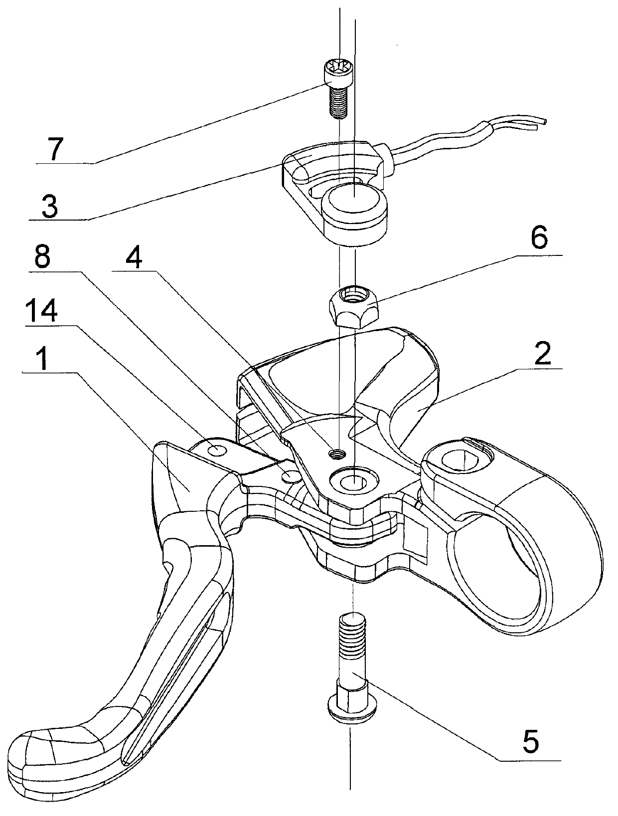
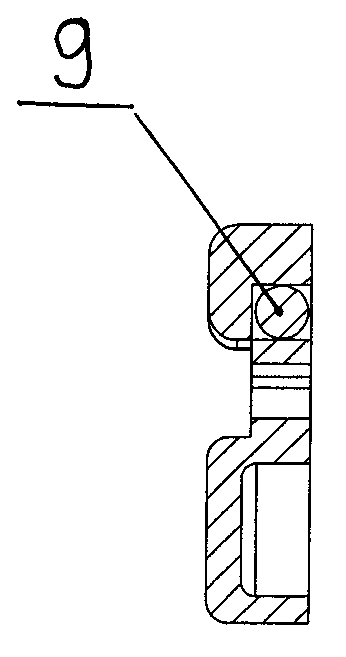
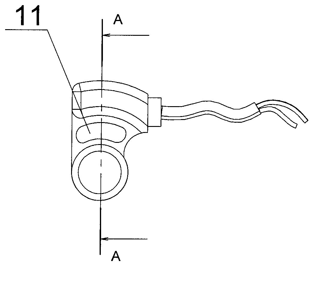
[0016] figure 1 , figure 2 , image 3 , Figure 4 and Figure 14 Shown in is a specific embodiment of the adjustable brake handle with switch of the present invention. Firstly, the adjustment of the induction position is explained: the handle 1 is installed in the handle seat 2 by the axial screw 5, and the fastening nut 6 fixes the axis The screw 5 is tightened and fixed, the handle 1 can rotate around the axis of the axial screw 5, the permanent magnet 8 on the handle 1 can also rotate around the axis of the axial screw 5 along with the handle 1, the movement of the permanent magnet 8 The track is an arc; the sensor assembly 3 is set on the fastening nut 6 and can rotate around the axis of the fastening nut 6 and the axial screw 5. The sensor assembly 3 has an adjusting arc groove 11 for adjustment and a dry spring The trajectory of the tube 9 and the reed switch 9 is als...


PUM


Abstract

The invention discloses an adjustable brake handle with a switch. The adjustable brake handle comprises a handle (1), a handle base (2), a sensor component (3), a permanent magnet (8), an axis screw (5), a clamp nut (6) and an adjusting screw (7), wherein both the handle (1) and the sensor component (3) rotate by taking the axial line of the axis screw (5) as the axis. The permanent magnet (8) is inlayed or adhered to the handle (1). The sensor component (3) is provided with an adjusting arc-shaped groove (11) for adjustment and a reed switch (9). The adjustable brake handle is more accurate to adjust, greatly increases the effective area of the switch, and is relatively miniature and light.

Description

technical field [0001] The invention relates to parts of an electric bicycle, in particular to a brake handle with a magnetic induction switch for braking. Background technique [0002] Electric bicycles are a huge amount of transportation, walking and fitness tools in the world. In order to adjust the speed and brake, the brake handle with switch is a necessary part. The induction type brake handle with switch widely used at present lacks precise adjustability. Chinese Utility Model Patent Application No. 201220081342.7 Authorized Announcement No. CN202624548U, titled: Patent for Adjustable Electric Induction Structure Started by Brake Handle, provides a relatively accurate adjustable brake handle with switch, and begins production and enters the market. The deficiencies of this patent are as follows: First, because the adjustment direction of the sensor in this solution is linear, but the motion trajectory of the magnetic body on the handle is not completely linear, it is...

Claims


Application Information

Patent Timeline
Patent Type & Authority Applications(China)
IPC IPC(8): B62L3/02
Inventor 张小红
Owner 张小红
Learn More