Electric folding landing gear and control method thereof

A landing gear, electric technology, applied in the field of landing gear, can solve the problems of low custom-made versatility, short service life, heavy weight, etc., to improve safety and effective service life, easy to disassemble and transport, easy to install and deploy Effect

Inactive Publication Date: 2014-08-06
郑荣武
View PDF5 Cites 12 Cited by
  • Summary
  • Abstract
  • Description
  • Claims
  • Application Information

AI Technical Summary

Problems solved by technology

[0003] At present, there are few mature retractable landing gear schemes, and the existing retractable landing gear has problems such as complex mechanism, high cost, small load-bearing, heavy weight, complicated installation, low versatility of tailor-made, and short service life.

Method used


Image

  • Electric folding landing gear and control method thereof
  • Electric folding landing gear and control method thereof
  • Electric folding landing gear and control method thereof

Examples


Embodiment 1

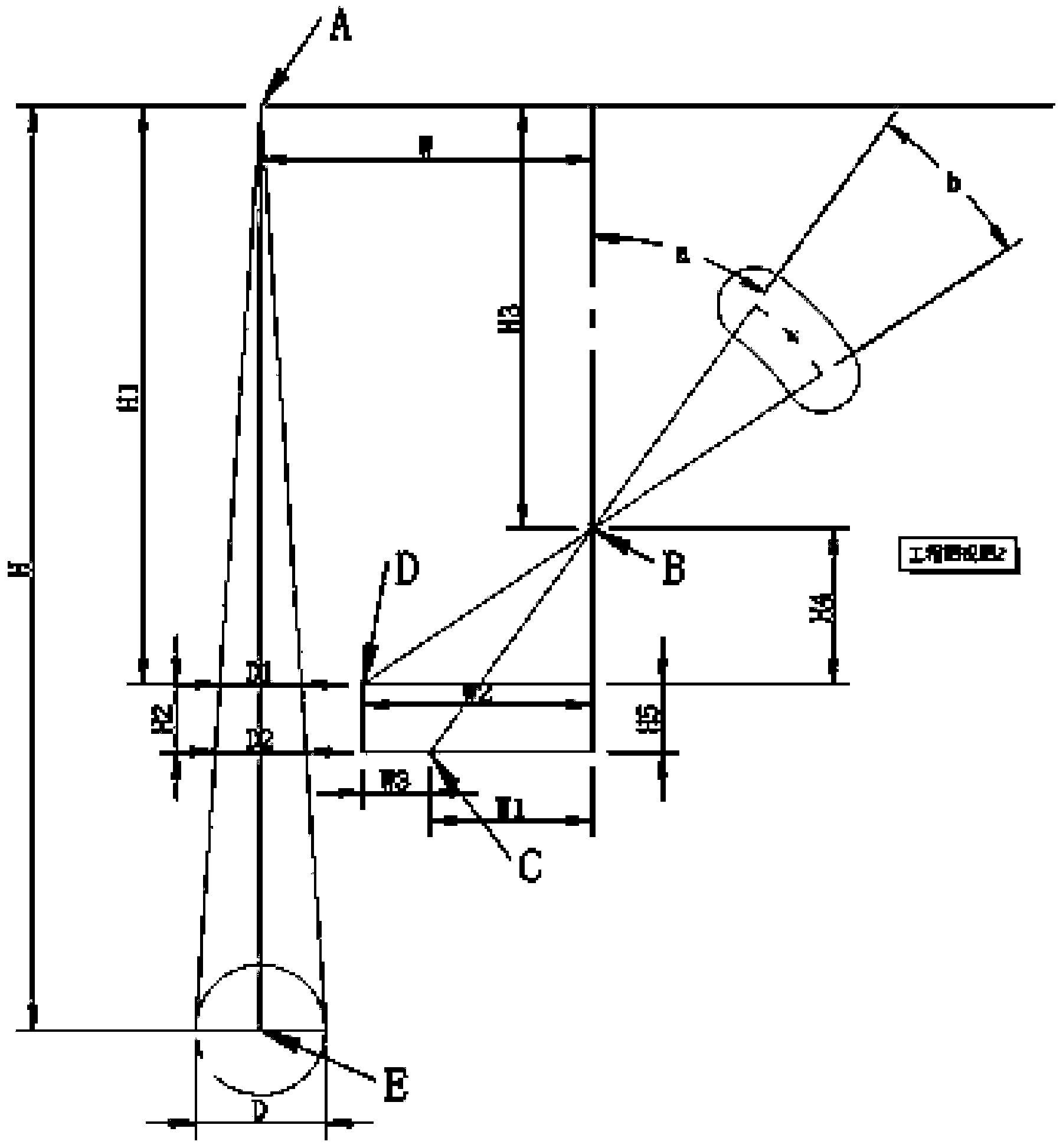
[0099] This embodiment provides an electrically retractable landing gear applicable to a vertical take-off and landing drone, including: a first support frame, a second support frame, a folding arm, a first locking member, a control board and a steering gear assembly. The electric retractable landing gear is powered by 5-7V DC power supply. The user's control command is connected to the control board through the signal line. After the control board is processed, the control board drives the steering gear assembly to move forward or backward according to a specific speed and angle. Reverse rotation, and then drive the mechanical structure of the landing gear to realize a series of actions such as retracting, lowering, locking and unlocking of the landing gear. Such as figure 1 As shown in , it is the left side view of the retracted state of the landing gear, such as figure 2 Shown is the left side view of the landing gear down state.

[0100] Such as image 3 Shown is a par...

Embodiment 2

[0135] The basic principle of this embodiment is the same as that of Embodiment 1, and the similarities with Embodiment 1 will not be repeated here. The following three differences are mainly introduced:

[0136] Difference one:

[0137] The second supporting frame is different from the first embodiment.

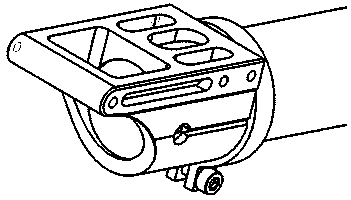
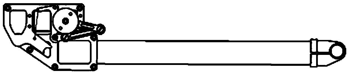
[0138] Such as Figure 22 As shown, it is a partially enlarged view of the electrically retractable landing gear, and 7a is the second support frame of this embodiment. Such as Figure 23 As shown, it is a partial structural schematic diagram of the second support frame, and the second support frame adopts an integrated movable pipe seat. The movable pipe seat mainly has five functions: one is to fix the main load-bearing carbon fiber tube in the longitudinal direction of the landing gear; the other is to provide the rotation positioning fulcrum for the left and right support arms; Fix the left and right brackets so that the laterally tensioned fixing points of the left ...


PUM


Abstract

The invention provides an electric folding landing gear and a control method thereof. The electric folding landing gear comprises a first support frame, a second support frame, a folding arm, a first locking piece, a control board and a steering gear component, wherein the folding arm comprises a left folding branch arm and a right folding branch arm; the end A of the left branch arm is rotatably arranged on the left surface of the second support frame; the end B of the left branch arm is provided with a first arc-shaped rabbet; the bottom surface of a tiller is fixedly provided with a first push column and a second push column; the first push column is positioned in the first arc-shaped rabbet; the second push column is opposite to the bent part of the first locking piece; by virtue of cooperation of the second push column and the bent part, the stroke caused by pushing a lock hook to be away from a hanging column so as to rotate by the second push column is shorter than the total rotation stroke of the first push column in the first arc-shaped trough. The electric folding landing gear has the advantages of concise mechanism, low construction cost, light weight, high load bearing capacity, easiness for installation and deployment, high safety, strong universality and low energy consumption. The electric folding landing gear is especially capable of realizing asynchronous running of folding and unfolding actions of the landing gear and the rotation of the steering gear, and improving the use safety of the electric landing gear.

Description

technical field [0001] The invention relates to a landing gear, in particular to an electrically retractable landing gear and a manipulation method thereof. Background technique [0002] With the acceleration of the civilianization process of drone technology, multi-rotor aircraft, or drones, have begun to be used in all walks of life, especially in the field of aerial photography. Aerial video photography requires the aircraft to be equipped with a retractable landing gear, so as to prevent part of the aircraft itself from being captured in the image during the video shooting process. [0003] At present, there are few mature retractable landing gear schemes, and the existing retractable landing gear has problems such as complex mechanism, high cost, small load-bearing, heavy weight, complicated installation, low versatility of tailor-made, and short service life. Contents of the invention [0004] Aiming at the defects existing in the prior art, the present invention pr...

Claims


Application Information

Patent Timeline
Patent Type & Authority Applications(China)
IPC IPC(8): B64C25/10B64C25/24
Inventor 不公告发明人
Owner 郑荣武
Why Eureka
Try Eureka