
Fluid regulator with integrated rapid pressurization bypass valve

A regulator, bypass flow path technology, used in auxiliary non-electrical fluid pressure control, valve details, fluid pressure control, etc., can solve problems such as taking longer time

Active Publication Date: 2014-08-06
TESCOM CORP
View PDF7 Cites 5 Cited by
  • Summary
  • Abstract
  • Description
  • Claims
  • Application Information

AI Technical Summary

Problems solved by technology

Typical regulators are not designed to handle these flows, and, moreover, it takes longer to pressurize than

Method used


Image

  • Fluid regulator with integrated rapid pressurization bypass valve
  • Fluid regulator with integrated rapid pressurization bypass valve
  • Fluid regulator with integrated rapid pressurization bypass valve

Examples


Embodiment Construction

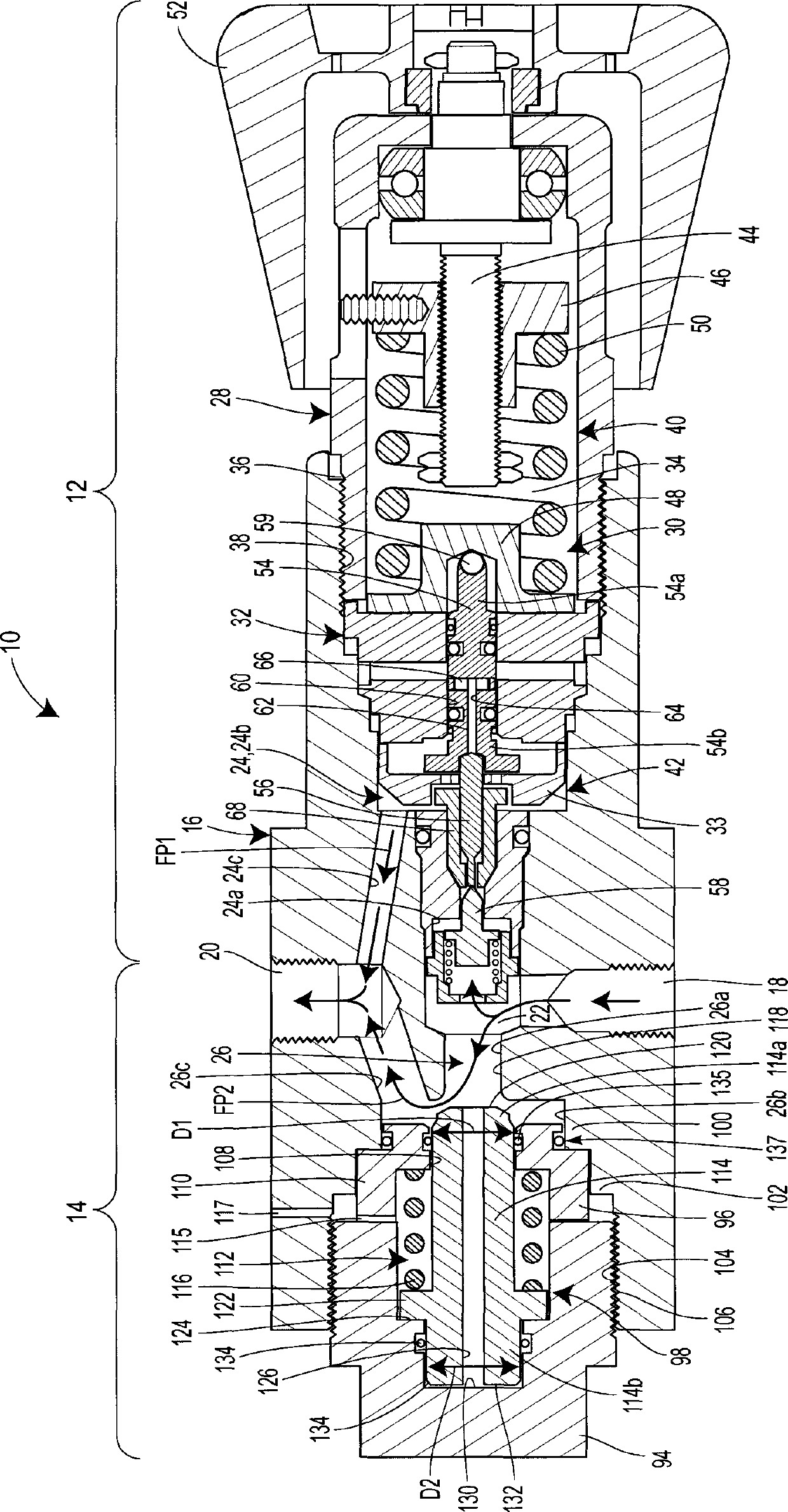
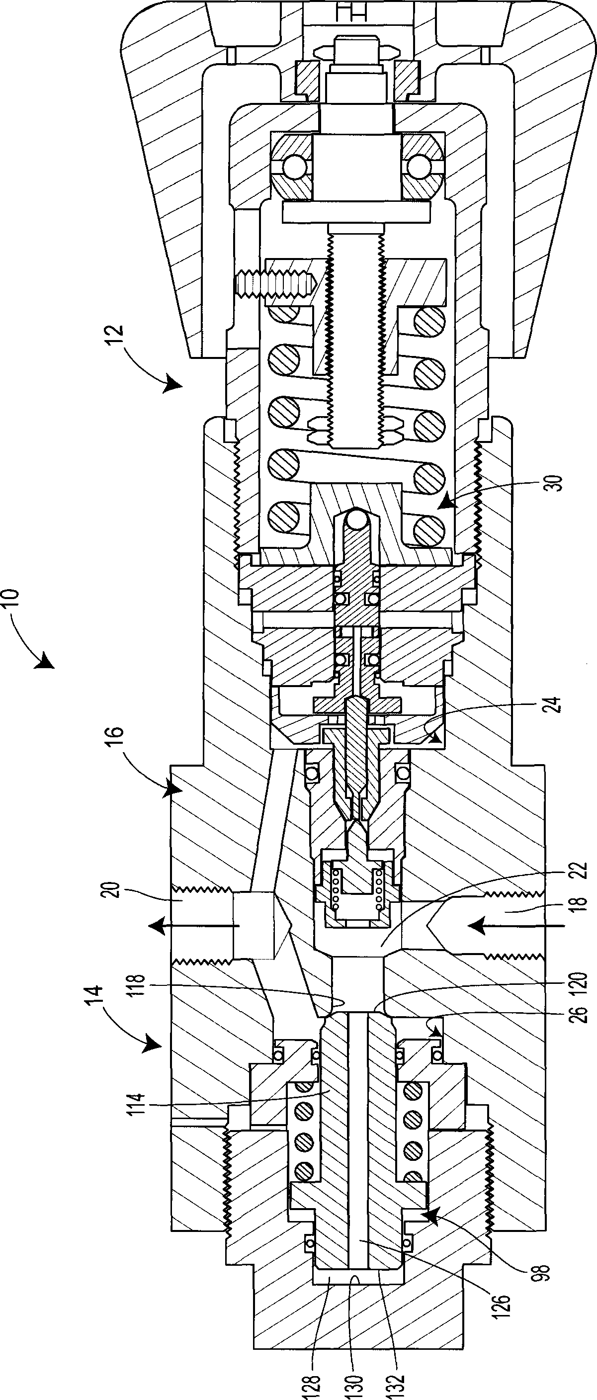
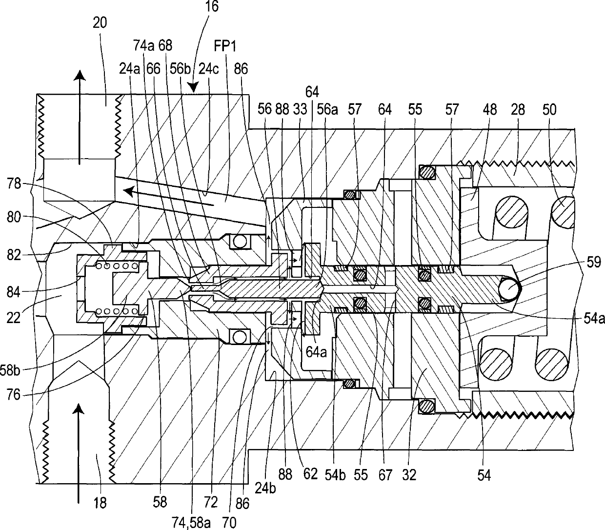
[0019] The present disclosure relates to a fluid flow control device that includes a regulator with an integrated bypass valve for protecting the regulator from exposure to high velocity and high pressure intense fluid flow under certain operating conditions. The regulator and the bypass valve are connected by a common valve body defining an inlet and an outlet. The regulator and the bypass valve each include a regulator flow path and a bypass flow path, respectively, for controlling the flow of fluid along the respective regulator and bypass flow paths that communicate between the inlet and the outlet of the valve body. Each control assembly is naturally biased to an open position so as not to prevent fluid flow through the flow path. Furthermore, the control assembly does not move out of the open position and into the closed position until the fluid pressure in the valve body rises above the relevant set point pressure. For example, in one case, a spring biases the bypass c...


PUM


Abstract

A fluid flow control device includes a regulator for operating at high pressures and an integral bypass valve. The regulator and the bypass valve each include a control assembly that is movable between an open position and a closed position. The regulator and bypass valves are biased into the open positions and adapted to move into the closed positions when an operating pressure rises to above respective regulator and bypass set-point pressures. The bypass set-point pressure is lower than the regulator set-point pressure such that when the operating pressure rises above the bypass set-point pressure, the bypass valve automatically closes and allows the regulator to perform under normal operating conditions. So configured, the bypass valve is arranged to accommodate at least some of the fluid flow through the system until the operating pressure reaches the normal operating pressure, which is somewhere between the bypass and regulator set-point pressures.

Description

technical field [0001] The present disclosure relates to fluid regulators, and more particularly, to fluid regulators for use in systems requiring rapid pressurization. Background technique [0002] Fluid flow control devices, such as fluid regulators, are commonly used in a variety of applications to ensure that fluid is delivered from a source to a destination without exceeding a predetermined control pressure. That is, a typical pressure regulator reduces the pressure of the fluid from the source to a control pressure suitable for the intended application. [0003] Typically, regulators are used in continuously pressurized systems. For example, in the offshore oil and gas industry, hydraulic regulators are incorporated into integrated lines that supply high pressure hydraulic fluid to subsea equipment miles away. In normal operation, the manifold is filled with fluid and pre-pressurized so that the regulator simply operates to ensure that the pressure in the manifold do...

Claims


Application Information

Patent Timeline
IPC IPC(8): F16K17/22F16K31/36F16K37/00
CPCG05D16/16G05D7/0133G05D16/0404G05D16/107Y10T137/0368Y10T137/7759Y10T137/8733F16K17/00
Inventor T·W·拉森C·R·柯克纳G·C·缪尔
Owner TESCOM CORP
Learn More