
Heat preservation water tank capable of efficiently storing and utilizing solar energy heat through automatic separation and combination manners

A technology of thermal insulation water tank and water storage tank, which is applied in the directions of solar thermal power generation, solar thermal device, heating device, etc., can solve the problems of high electricity consumption and long heating time, and achieve the effect of convenient use.

Inactive Publication Date: 2014-08-06
周才强
View PDF7 Cites 1 Cited by
  • Summary
  • Abstract
  • Description
  • Claims
  • Application Information

AI Technical Summary

Problems solved by technology

[0003] In order to overcome the problems of the existing solar water heater auxiliary electric heating that takes a long time, consumes a lot of electricity, gets colder with washing, hot water cannot be fully utilized, and heat energy is wasted a lot, the present invention provides a separate solar thermal insulation water tank, which can not only solve the problem of The existing solar heat preservation water tank has the problems of long time-consuming auxiliary electric heating, high electricity consumption, and the colder it gets after washing, and it can fully utilize the hot water in the tank and efficiently store the solar heat absorbed by the heat collecting tube, thus improving the heat utilization rate of solar energy

Method used


Image

  • Heat preservation water tank capable of efficiently storing and utilizing solar energy heat through automatic separation and combination manners

Examples


Embodiment Construction

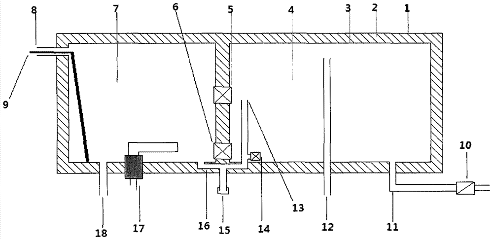
[0011] exist figure 1 Among them, two independent inner water tanks are set, which are the first-level water storage tank (4) and the second-level water storage tank (7), and the first-level water storage tank (4) is provided with a cold water inlet (11) and an overflow pipe concurrently Air port (12), auxiliary electric heating (17) and hot water outlet (18) are set in the second-level water storage tank (7), set between the first-level water storage tank (4) and the second-level water storage tank (7) Two convection openings are equipped with convection temperature control switch (5) (6) respectively, and the first-level water storage tank (4) and the second-level water storage tank (7) are connected with the U-shaped pipe (16). A tee is connected at the joint between the bottom of the first-level water storage tank (4) and the mouth of the U-shaped pipe (16). Extend the extension pipe (13) to the upper middle position of the water tank. The setting temperature of the conv...


PUM


Abstract

The invention discloses a heat preservation water tank capable of efficiently storing and utilizing solar energy heat through automatic separation and combination manners. The heat preservation water tank is composed of an outer tank, a heat preservation layer, a first level water storing tank, a second water storing tank, a cold water inlet, an overflow hole which is utilized as an exhaust hole, an auxiliary electrical heating device, a hot water outlet, the exhaust hole, a U-shaped pipe sewage draining hole, a temperature controlled switch, a U-shaped pipe and an extending pipe, wherein two convection holes are formed between the two water tanks and are respectively provided with a convection temperature controlled switch, so that heat use ratio of solar energy is improved when the sunlight is not good, and heat storage volume of solar energy is improved when the sunlight intensity is high; one end of the U-shaped pipe is provided with a small temperature controlled switch and the extending pipe, a condition that water in the two water tanks is not mixed when the water tanks are electrically heated in rainy days is guaranteed, when the hot water is used, cold water can not enter the water tank, and the water in the two water tanks is used up in sunny day, so that the problem that abundant time and electricity are consumed during electric heating by the one-tank solar water heater is solved, and the problems that when a common two-tank solar water heater is used, cold water enters while hot water is used, so that the hot water can not be completely utilized, and the energy utilization rate is low are also solved.

Description

technical field [0001] The invention relates to a solar thermal insulation water tank, in particular to a sub-compartment solar thermal thermal insulation water tank with auxiliary electric heating. Background technique [0002] At present, the solar thermal insulation water tanks on the market are either non-compartment solar thermal thermal water tanks or sub-compartment solar thermal thermal water tanks with automatic water replenishment. The solar thermal insulation water tank without compartments has a large volume, and it takes a long time to use auxiliary electric heating in rainy weather and consumes a lot of electricity; although the compartmentalized solar thermal thermal water tank with automatic water replenishment solves the problem of the long time-consuming auxiliary electric heating of solar thermal thermal water tanks without compartments However, there are new problems: first, because it will automatically replenish water, it will become colder and colder w...

Claims


Application Information

Patent Timeline
IPC IPC(8): F24J2/46F24J2/00
CPCY02E10/40
Inventor 周才强
Owner 周才强
Learn More