Supercharge Your Innovation With Domain-Expert AI Agents!

Focus adjusting optical lens assembly

An optical lens group and lens technology, applied in optics, optical components, instruments, etc., can solve the problems of image quality degradation, miniaturized lenses that are difficult to satisfy both long-range shooting and close-up shooting, peripheral image blurring and image quality, etc.

Active Publication Date: 2014-08-06
LARGAN PRECISION
View PDF5 Cites 7 Cited by
  • Summary
  • Abstract
  • Description
  • Claims
  • Application Information

AI Technical Summary

Problems solved by technology

Generally speaking, due to space constraints, it is difficult for miniaturized lenses to meet the needs of both telephoto and close-up shots
For example, the five-element lens group disclosed in U.S. Patent No. 7,864,454 is a moving focus mode of the entire lens group, and its focal depth is limited in close-up shots, which tends to blur peripheral images and cause image quality defects
[0003] In addition, for photographic lenses with adjustable focus functions, the focus adjustment method can be processed by software, such as Extended Depth of Field technology (EDoF, Extended Depth of Field) uses the color of the best light shape at the current distance as the main axis light Then use digital simulation to achieve the focusing effect, or use the voice coil motor (Voice Coil Motor, VCM) to change the relative distance between the overall photographic lens and the image sensor to achieve the focusing effect, but the above two methods have image quality degradation and consumption. Problems such as excessive power

Method used


Image

  • Focus adjusting optical lens assembly
  • Focus adjusting optical lens assembly
  • Focus adjusting optical lens assembly

Examples


no. 1 example

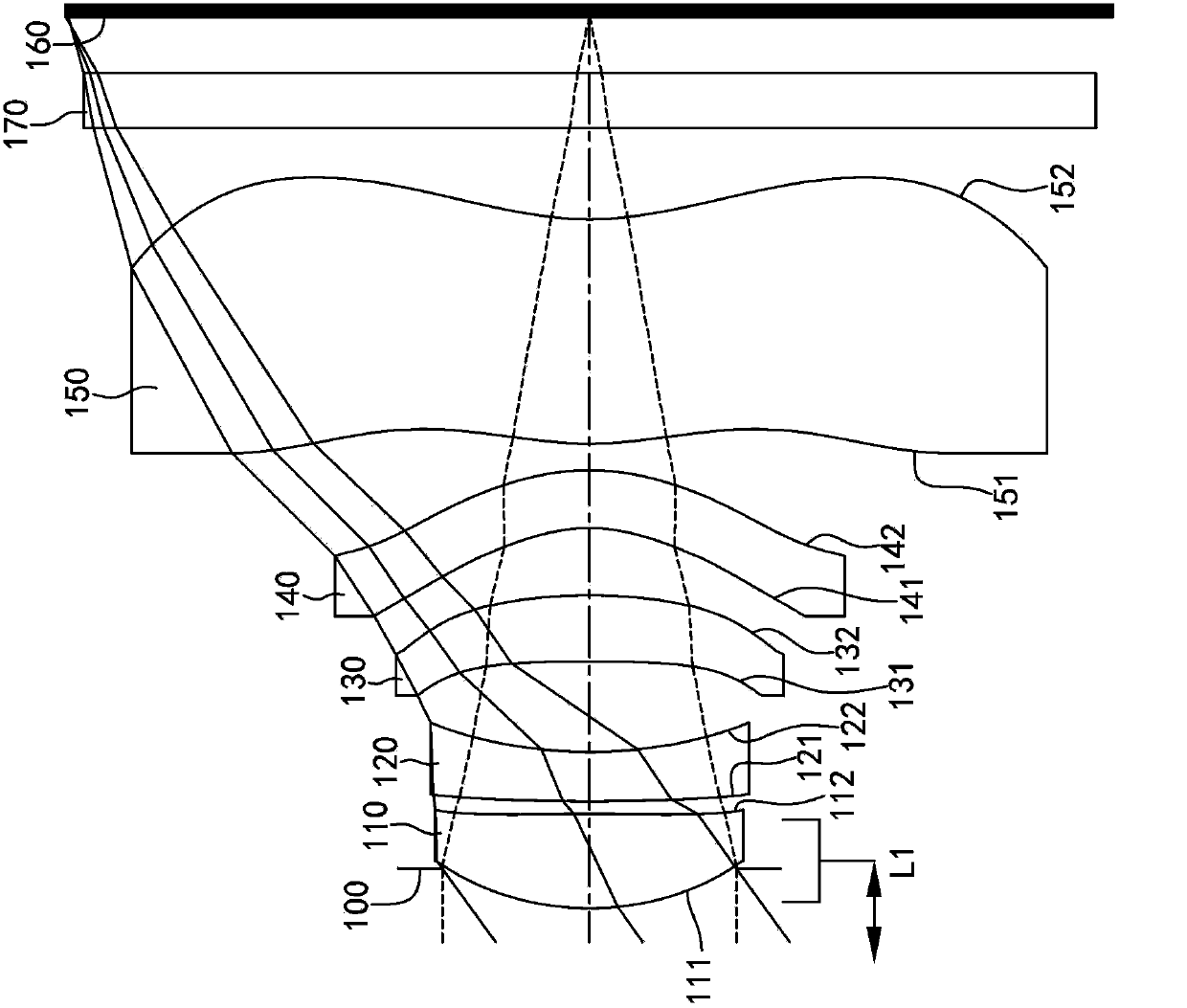
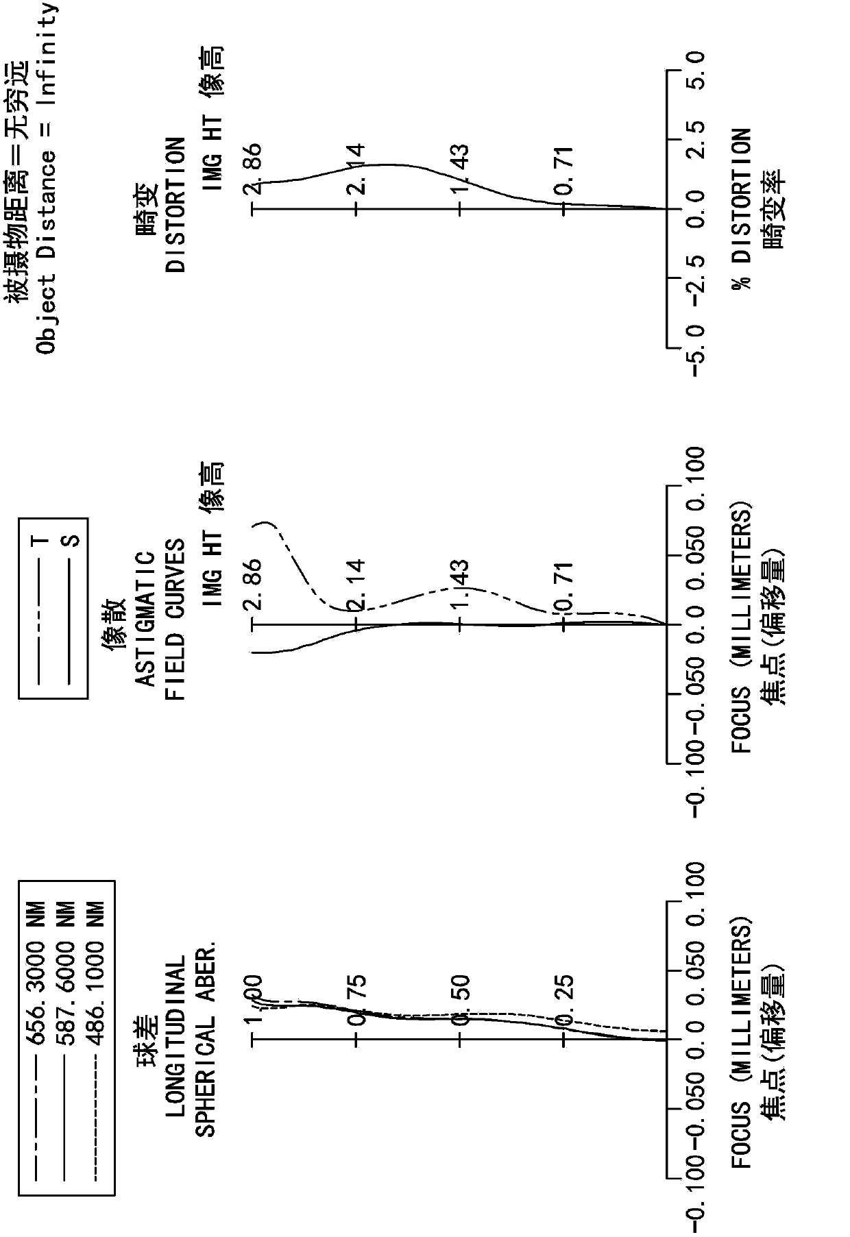
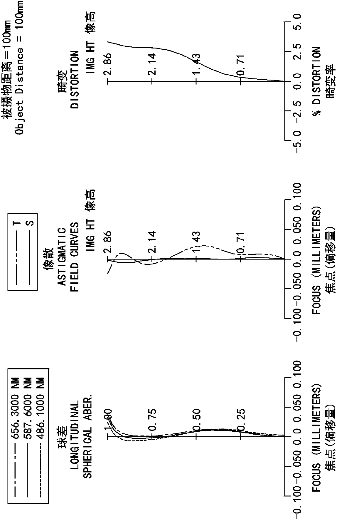
[0101] Please refer to figure 1 , Figure 2A and Figure 2B ,among them figure 1 A schematic diagram of a moving focusing optical lens group according to the first embodiment of the present invention is shown, Figure 2A From left to right, the spherical aberration, astigmatism and distortion curves of the moving focus optical lens group of the first embodiment in telephoto (the subject distance is infinite) in sequence, Figure 2B From left to right, the spherical aberration, astigmatism, and distortion curves of the moving focus optical lens group of the first embodiment in close-up shooting (the subject distance is 100mm) are shown in sequence. by figure 1 It can be seen that the moving focusing optical lens group includes the aperture 100, the first lens 110, the second lens 120, the third lens 130, the fourth lens 140, the fifth lens 150, and the infrared filter in order from the object side to the image side. (IR-Cut Filter) 170 and imaging surface 160. Among them, there a...

no. 2 example

[0138] Please refer to image 3 , Figure 4A and Figure 4B ,among them image 3 A schematic diagram of a moving focusing optical lens group according to the second embodiment of the present invention is shown, Figure 4A Sequentially from left to right, are the spherical aberration, astigmatism and distortion curves of the moving focus optical lens set of the second embodiment in telephoto (the subject distance is infinite). Figure 4B From left to right, the spherical aberration, astigmatism, and distortion curves of the moving focus optical lens group of the second embodiment in close-up shots (the subject distance is 100mm) are shown in sequence. by image 3 It can be seen that the moving focusing optical lens group includes the aperture 200, the first lens 210, the second lens 220, the third lens 230, the fourth lens 240, the fifth lens 250, and the infrared filter in order from the object side to the image side. 270 and imaging surface 260. Among them, there are five lense...

no. 3 example

[0154] Please refer to Figure 5 , Figure 6A and Figure 6B ,among them Figure 5 A schematic diagram of a moving focusing optical lens group according to the third embodiment of the present invention is shown, Figure 6A From left to right, the spherical aberration, astigmatism and distortion curves of the moving focus optical lens group of the third embodiment in telephoto (the subject distance is infinite) in sequence, Figure 6B From left to right, the spherical aberration, astigmatism, and distortion curves of the moving focus optical lens set of the third embodiment in close-up photography (the subject distance is 100mm) are shown in sequence. by Figure 5 It can be seen that the moving focusing optical lens group includes the aperture 300, the first lens 310, the second lens 320, the third lens 330, the fourth lens 340, the fifth lens 350, and the infrared filter in order from the object side to the image side. 370 and imaging surface 360. Among them, there are five lens...


PUM


Abstract

A focus adjusting optical lens assembly includes, in order from an object side to an image side, a first lens element, a second lens element, a third lens element, a fourth lens element and a fifth lens element. The first lens element with positive refractive power has a convex object-side surface. The second lens element has negative refractive power. The third lens element has refractive power. The fourth lens element with negative refractive power has a concave object-side surface and a convex image-side surface. The fifth lens element has a concave image-side surface at a paraxial region, wherein the image-side surface of the fifth lens element changes from concave at the paraxial region to convex at a peripheral region, and both of an object-side surface and the image-side surface of the fifth lens element are aspheric. In switching of remote photographing and close photographing, focus adjustiment is executed by means of adjusting a spacing distance between the first lens and the second lens on the optical axis. The focusing problem in remote photographing and close photographing can be improved when specific conditions are satisfied, and the characteristics of small size and low power can be achieved at the same time.

Description

Technical field [0001] The invention relates to a mobile focusing optical lens group, in particular to a miniaturized mobile focusing optical lens group applied to electronic products. Background technique [0002] As personal electronic products become thinner and lighter, the size of the internal components of the product also needs to be reduced, especially in the volume of the camera lens module. Generally speaking, due to space constraints, it is difficult for miniaturized lenses to meet the needs of both long and close shots. For example, the five-element lens group disclosed in US Patent No. 7,864,454 is a moving focus mode for the entire lens group, and its focal depth at close-up is limited, which easily blurs surrounding images and causes image quality defects. [0003] In addition, generally, a photographic lens with a focus adjustment function can be adjusted by software, such as Extended Depth of Field (EDoF, Extended Depth of Field), which uses the color of the best ...

Claims


Application Information

Patent Timeline
Patent Type & Authority Applications(China)
IPC IPC(8): G02B13/18G02B13/00G02B1/04
CPCG02B13/0045G02B9/60
Inventor 蔡宗翰陈纬彧
Owner LARGAN PRECISION
Features
  • R&D
  • Intellectual Property
  • Life Sciences
  • Materials
  • Tech Scout
  • Unparalleled Data Quality
  • Higher Quality Content
  • 60% Fewer Hallucinations
Learn More