Control method and system for power electronic transformer

A technology of power electronics and control methods, applied to AC networks to reduce harmonics/ripples, reactive power compensation, harmonic reduction devices, etc., can solve problems such as increasing costs

Active Publication Date: 2014-08-06
ELECTRIC POWER RES INST OF GUANGXI POWER GRID CO LTD +1
View PDF4 Cites 14 Cited by
  • Summary
  • Abstract
  • Description
  • Claims
  • Application Information

AI Technical Summary

Problems solved by technology

[0004] Combining the existing PET and traditional transformer parallel technology, only the suppression of the circulating current of the parallel system can be realized. If the power quality is to be adjusted, static var compensators, active filters and other devices need to be added to the line, which increases the cost

Method used


Image

  • Control method and system for power electronic transformer
  • Control method and system for power electronic transformer
  • Control method and system for power electronic transformer

Examples


Embodiment 1

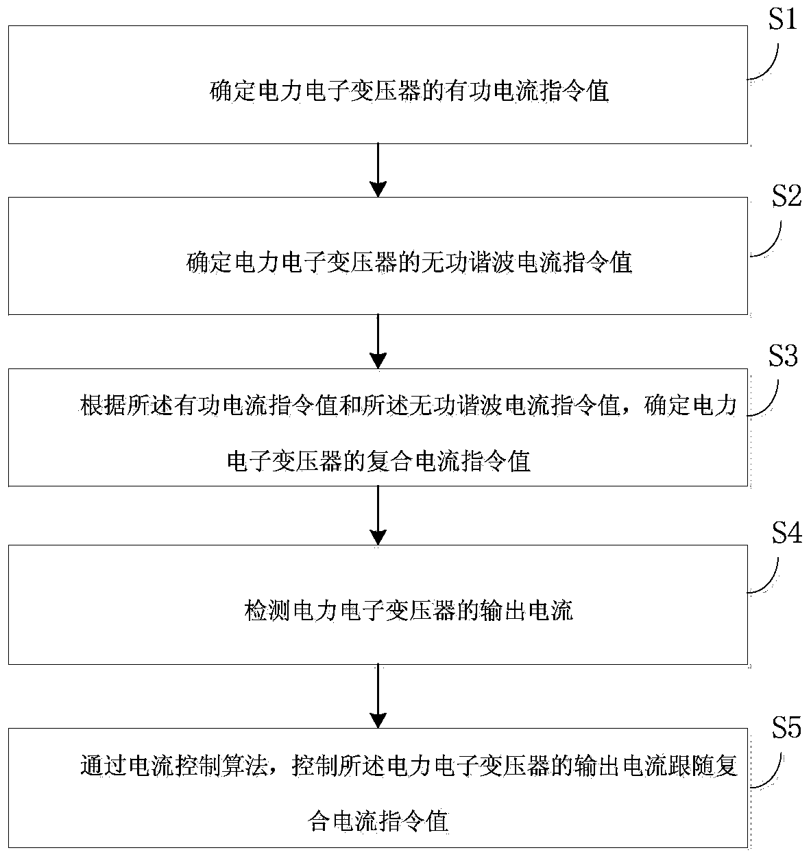
[0067] An embodiment of the present invention provides a control method for a power electronic transformer, see figure 1 , the method includes the following steps:

[0068] S1. Determine the active current command value of the power electronic transformer;

[0069] S2. Determine the reactive harmonic current command value of the power electronic transformer;

[0070] S3. Determine the composite current command value of the power electronic transformer according to the active current command value and the reactive harmonic current command value;

[0071] S4. Detect the output current of the power electronic transformer;

[0072] S5. Using a current control algorithm, controlling the output current of the power electronic transformer to follow the change of the composite current command value.

[0073] For example, when the load changes, the active current command value is changed through its own adjustment effect. Similarly, the reactive harmonic current command value can be...

Embodiment 2

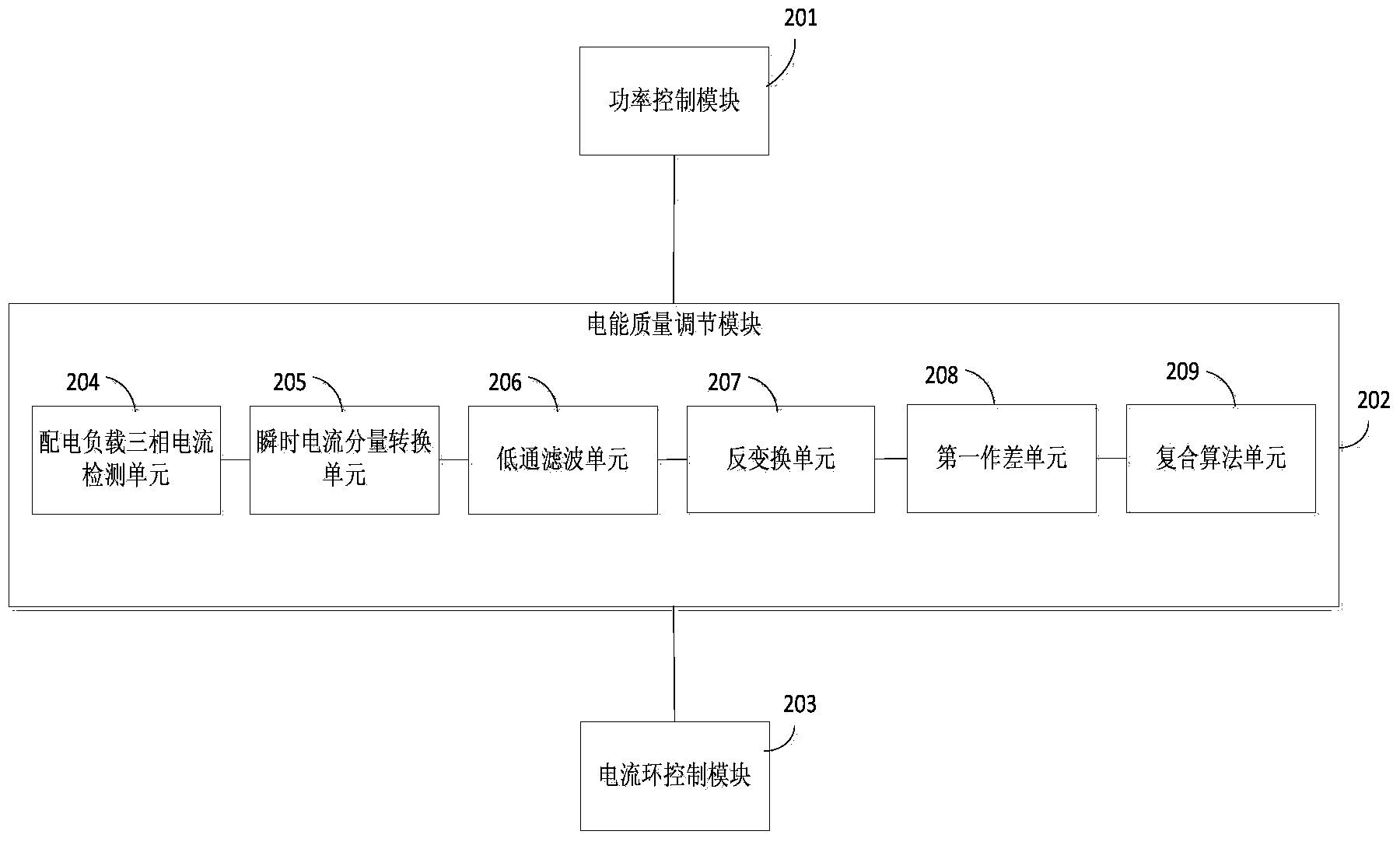
[0095] The embodiment of the present invention also provides a control system for a power electronic transformer, see figure 2 , including the following modules:

[0096] The power control module 201 is used to control the output active power of the power electronic transformer according to the load power prediction value and the output power value of the traditional transformer, so as to determine and control the active current command value of the power electronic transformer.

[0097] Specifically, detect the parallel bus voltage and the output current of the traditional transformer, obtain the output power of the traditional transformer, predict the active power required by the load, use the P-Q algorithm to obtain the active power that the power electronic transformer needs to output, and obtain the active current command value of the power electronic transformer .

[0098] The power quality adjustment module 202 is configured to determine a reactive harmonic current co...

Embodiment 3

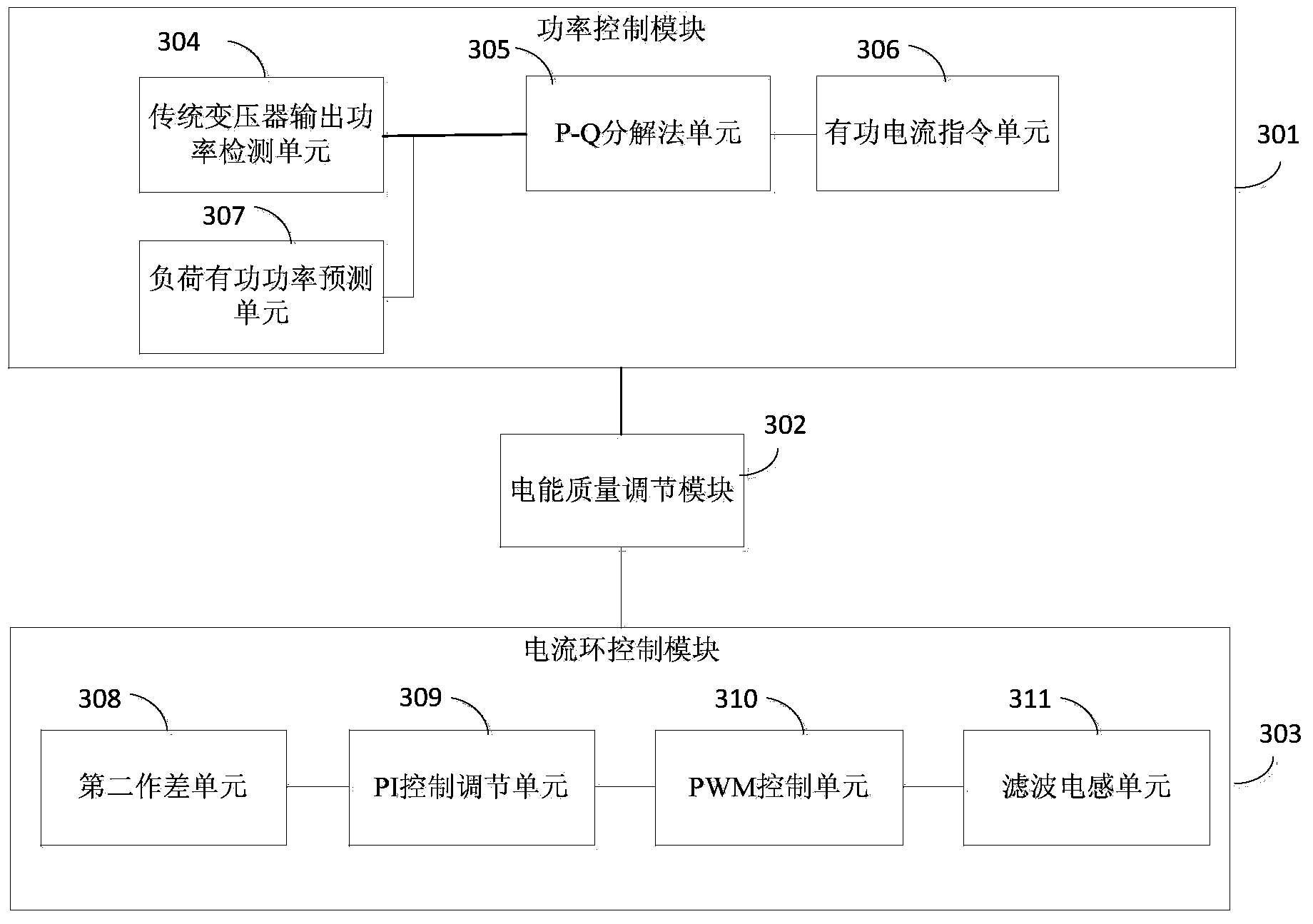
[0114] The embodiment of the present invention also provides a power electronic transformer control system, see image 3 , including the following modules:

[0115] The power control module 301 is used to detect the parallel bus voltage and the output current of the traditional transformer, obtain the output power of the traditional transformer, predict the active power required by the load, use the P-Q algorithm to obtain the active power to be output by the power electronic transformer, and obtain the power electronic transformer active current command value.

[0116] The power quality adjustment module 302 is used to detect the distribution load current, using i p -i q The reactive power and harmonic current in the distribution network are obtained by the method, the reactive harmonic current command value is generated, and the composite current command value of the power electronic transformer is synthesized by using a composite algorithm;

[0117] The current loop cont...


PUM


Abstract

The invention provides a control method and system for a power electronic transformer. The method includes the steps that S1, an active current instruction value of the power electronic transformer is determined, and active power which the power electronic transformer needs to output is controlled; S2, a reactive harmonic current instruction value of the power electronic transformer is determined; S3, according to the active current instruction value and the reactive harmonic current instruction value, a recombination current instruction value of the power electronic transformer is determined; S4, the current of the power electronic transformer is detected; S5, the output current of the power electronic transformer is controlled to follow the recombination current instruction value through a current control algorithm. The power electronic transformer and a traditional transformer operate in a parallel connection mode, while the load active power is provided, the quality of electric energy of a low-voltage grid is adjusted, distribution network contamination is eliminated, and stability and power supply reliability of a power distribution system are improved.

Description

technical field [0001] The invention relates to the field of power electronic control, in particular to a control method and system for a power electronic transformer. Background technique [0002] Parallel operation of traditional transformers is common in power systems. With the emergence of a large number of nonlinear and impact loads, the harmonics and reactive currents generated by these loads are increasingly polluting the public grid. Static var compensation is generally required and active filter devices for reactive power compensation and harmonic suppression. But this will make the system relatively large, and there will be circulation problems at the same time. Power electronic transformer (PET) is a kind of power transformer with strong controllability. It is small in size and light in weight. The influence of the grid side realizes the decoupling of the grid side and the load side. However, compared with traditional transformers, PET is expensive at this stag...

Claims


Application Information

Patent Timeline
Patent Type & Authority Applications(China)
IPC IPC(8): H02J3/01H02J3/18
CPCY02E40/30Y02E40/40
Inventor 周柯陈立赵坚奉斌帅智康杨晶晶许飞徐波吴丽芳欧世峰金庆忍楚红波
Owner ELECTRIC POWER RES INST OF GUANGXI POWER GRID CO LTD
Why Eureka
Try Eureka