
A method and device for maintaining time slot state information

A state information and time slot technology, which is applied in the field of network management, can solve the problems of system confusion, the receiving node cannot demodulate useful signals, and the channel environment changes greatly. The effect of accuracy

Active Publication Date: 2016-12-28
DATANG GOHIGH INTELLIGENT & CONNECTED TECH (CHONGQING) CO LTD
View PDF4 Cites 0 Cited by
  • Summary
  • Abstract
  • Description
  • Claims
  • Application Information

AI Technical Summary

Problems solved by technology

However, in the actual environment, the receiving node does not receive FI. There are three possibilities: one is that there is indeed no node in the network occupying the time slot, and the time slot resource is idle at this time; the second case may be due to two Nodes occupy the same time slot at the same time, so that the receiving node cannot correctly demodulate FI. In this case, if the physical layer energy detection is performed, it can be found that there is a strong signal in this time slot, but the receiving node cannot demodulate useful signals; In the three cases, the receiving node may not be able to demodulate FI correctly due to factors such as high-speed movement of the vehicle and large changes in the channel environment. In this case, through physical layer energy detection, it can be found that there is a strong signal in this time slot, but the receiving node No useful signal can be demodulated
[0006] At present, when the latter two situations occur, the receiving node cannot correctly demodulate FI, which is equivalent to receiving a strong interference signal in the corresponding time slot. At this time, the receiving node cannot correctly maintain the corresponding time slot state information, which will cause The system is chaotic, which seriously affects the system performance and increases the unsafety of road driving

Method used


Image

  • A method and device for maintaining time slot state information
  • A method and device for maintaining time slot state information
  • A method and device for maintaining time slot state information

Examples


Embodiment Construction

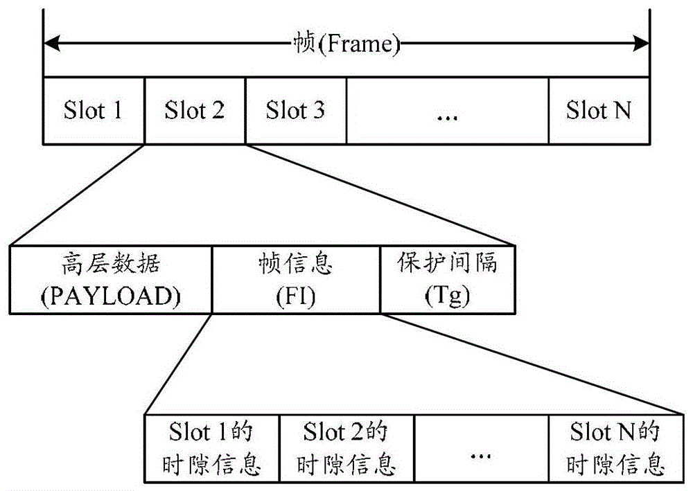
[0025] For the convenience of subsequent descriptions, the following description methods are uniformly adopted for FI and its internal information content in the embodiment of the present invention:

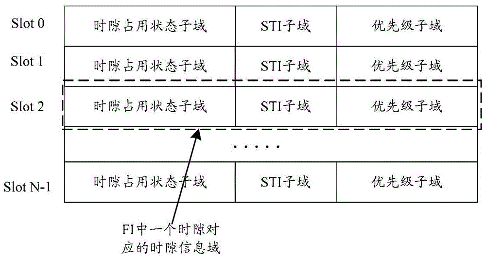
[0026] The occupancy status information corresponding to each time slot indicated in the FI (also called FI message) sent between nodes is called: the time slot information field corresponding to each time slot in FI;

[0027] The three types of information given in the occupancy status information corresponding to each slot in FI (ie: slot occupancy status, STI, and priority information) are respectively called: the slots contained in the slot information field of each slot occupancy state subfield, STI subfield, priority subfield;

[0028] It should be noted that the foregoing description manner is only specified for the convenience of subsequent descriptions, and of course other description manners may also be used.

[0029] In the embodiment of the present invention, in the ...


PUM


Abstract

The invention relates to network managing technologies, discloses a method and a device for maintaining time slot state information, and aims to increase maintenance accuracy of time slot state information and increase vehicle driving safety. The method includes: when the signal strength of a signal received by a node from time slot n not occupied by the node is larger than or equal to the preset signal threshold and FI cannot be analyzed accurately, the node sets the time slot state, contained in FI corresponding to time slot n, of the time slot n into a collision state, and updates local time slot state information corresponding to time slot n maintenance according to the setting result. Accordingly, other nodes can learn that the time slot n may collide according to the FI transmitted by the node and avoid to select the time slot n as self time slot, success rate of data packet receiving of each node is increased effectively, FI can be accurately analyzed to the maximum extent, maintenance accuracy of time slop state information is increased, and vehicle drive safety is increased.

Description

technical field [0001] The invention relates to network management technology, in particular to a method and device for maintaining time slot state information. Background technique [0002] With the development of in-vehicle communication systems and the gradual maturity of mobile ad hoc network technology, in order to realize real-time, dynamic and intelligent management of vehicles, the DSRC (Dedicated Short Range Communications) protocol for Internet of Vehicles has been specially developed internationally. . DSRC organically connects vehicles with vehicles, vehicles and roadside information collection equipment through two-way transmission of information, and supports point-to-point and point-to-multipoint communication. [0003] The mobile slotted ALOHA (Mobile Slotted Aloha, MS-ALOHA) mechanism is a DSRC MAC (Medium Access Control; Media Access Control) layer access and resource allocation mechanism based on time-sharing. Resource allocation is based on the frame str...

Claims


Application Information

Patent Timeline
Patent Type & Authority Patents(China)
IPC IPC(8): H04J3/16
Inventor 李凤冯媛房家奕赵毅赵丽
Owner DATANG GOHIGH INTELLIGENT & CONNECTED TECH (CHONGQING) CO LTD
Features
  • Generate Ideas
  • Intellectual Property
  • Life Sciences
  • Materials
  • Tech Scout
  • Unparalleled Data Quality
  • Higher Quality Content
  • 60% Fewer Hallucinations
Learn More