Multi-direction machining clamp for machining center

A machining center, multi-directional technology, applied in the direction of manufacturing tools, metal processing equipment, metal processing machinery parts, etc., can solve the problems of high labor intensity of staff, affecting the quality of parts processing, low processing efficiency, etc., to reduce work intensity, The effect of convenient processing and improving processing efficiency

Inactive Publication Date: 2014-08-13
WUXI XINHONGTAI ELECTRIC TECH CO LTD
View PDF8 Cites 5 Cited by
  • Summary
  • Abstract
  • Description
  • Claims
  • Application Information

AI Technical Summary

Problems solved by technology

[0002] At present, for the processing of box-type parts with two or more surfaces, the machining center generally adopts sequential clamping for surface-by-surface processing, which inevitably requires several clamping for the part, resulting in low processing efficiency and labor intensity of the staff. At the same time, there are corresponding processing size tolerance requirements between each processing surface, but multiple clamping will inevitably produce dimensional deviation, which will affect the processing quality of parts

Method used


Image

  • Multi-direction machining clamp for machining center
  • Multi-direction machining clamp for machining center

Examples


Embodiment Construction

[0014] The technical solutions of the present invention will be further described below in conjunction with the accompanying drawings and through specific implementation methods.

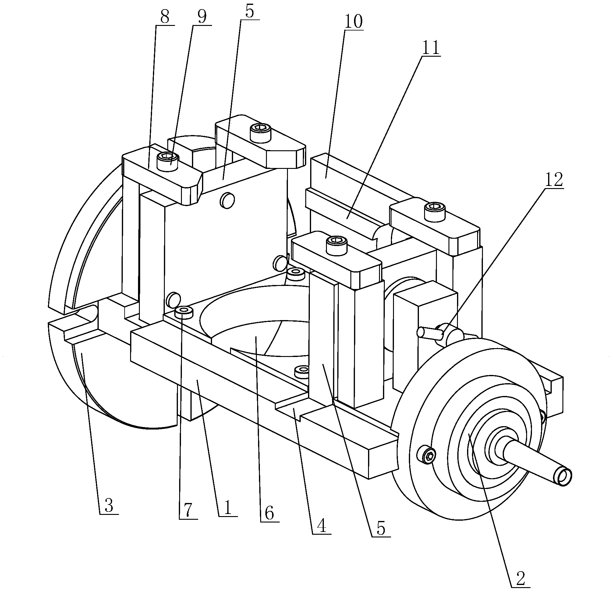
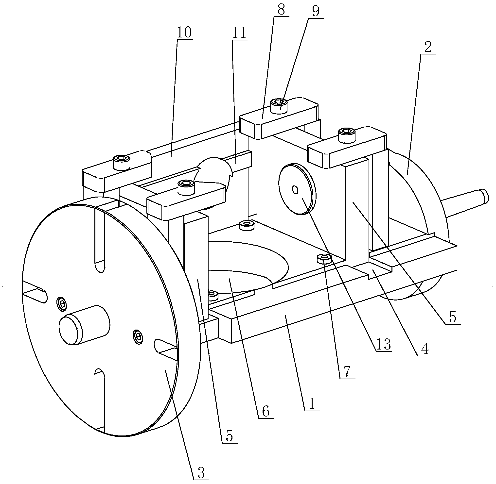
[0015] see figure 1 and figure 2 As shown, in this embodiment, a multi-directional machining fixture for a machining center includes a base plate 1, one end of the base plate 1 is connected with a Morse taper shank 2, and the other end is connected with a flange 3, and the base plate 1 is spaced in parallel. There are two installation grooves 4 perpendicular to the bottom plate 1, and a positioning plate 5 perpendicular to the bottom plate 1 is arranged in the installation groove 4, and a positioning plate 5 for processing parts is provided on the bottom plate 1 between the two positioning plates 5. The holes 6 are provided, and the four corners between the two positioning plates 5 on the bottom plate 1 are provided with positioning pins 7 for locating parts. The tops of the two positioning plate...


PUM


Abstract

The invention discloses a multi-direction machining clamp for a machining center. The multi-direction machining clamp for the machining center comprises a bottom plate, one end of the bottom plate is connected with a Morse taper shank, and the other end of the bottom plate is connected with a flange plate. The bottom plate is provided with two positioning plates perpendicular to the bottom plate in parallel in a spaced mode, and the bottom plate between the two positioning plates is provided with a hole used for machining parts. The tops of the two positioning plates are respectively provided with a pressing device used for limiting the parts, the position, placed on one sides of the two positioning plates, of the bottom plate is provided with a side plate, and the inner side face of the side plate is provided with a positioning convex edge used for positioning the parts. At lest one of the two positioning plates is provided with a fastening screw, the fastening screw penetrates through the positioning plate, and the end of the fastening screw is connected with a fastening plate. The multi-direction machining clamp for the machining center can achieve the purpose that box body type parts can achieve multi-face machining after one-time clamping, the working strength of workers is reduced, and working efficiency is improved.

Description

technical field [0001] The invention relates to a processing fixture, in particular to a multi-directional processing fixture for a machining center. Background technique [0002] At present, for the processing of box-type parts with two or more surfaces, the machining center generally adopts sequential clamping for surface-by-surface processing, which inevitably requires several clamping for the part, resulting in low processing efficiency and labor intensity of the staff. At the same time, there are corresponding processing size tolerance requirements between each processing surface, but multiple clamping will inevitably produce dimensional deviation, which will affect the processing quality of the parts. Contents of the invention [0003] The purpose of the present invention is to provide a multi-directional processing fixture for a machining center, which can process multiple surfaces of a part in one clamping, so as to solve the problem of processing the box-type part...

Claims


Application Information

Patent Timeline
Patent Type & Authority Applications(China)
IPC IPC(8): B23Q3/00
CPCB23Q3/00B23Q2703/02
Inventor 赵敏海邱伟峰刘明远
Owner WUXI XINHONGTAI ELECTRIC TECH CO LTD
Why Eureka
Try Eureka