Hydraulic automatic cleaning device for coal bunker and cleaning method thereof

A hydraulic automatic and coal bunker technology, applied in the field of mining machinery, can solve the problems of poor effect, low efficiency of mechanical dredging method, life of severe noise devices, etc., achieve accurate operation control throughout the whole process, reduce labor costs and hidden safety hazards, and improve work efficiency. Effect

Inactive Publication Date: 2014-08-13
李 长龙
View PDF8 Cites 8 Cited by
  • Summary
  • Abstract
  • Description
  • Claims
  • Application Information

AI Technical Summary

Problems solved by technology

[0005] The present invention aims at the problems of low efficiency and poor effect of the mechanical dredging method and unsatisfactory effect of the vibration dredging method when cleaning the coal bunker in the prior art, which requires continuous vibration, resulting in severe noise and short service life of the device, and provides A coal bunker hydraulic automatic plugging removal device and its cleaning method

Method used


Image

  • Hydraulic automatic cleaning device for coal bunker and cleaning method thereof
  • Hydraulic automatic cleaning device for coal bunker and cleaning method thereof

Examples


Embodiment 1

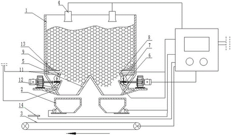
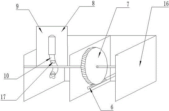
[0024] A coal bunker hydraulic automatic blockage removal device, which includes a coal storage bunker 1, two frequency conversion coal feeders 2, a belt conveyor 3, and a material level gauge 4 for monitoring the amount of coal stored above the coal storage bunker 1, including a PLC The control cabinet 15, the coal flow sensor 14 arranged above the belt conveyor 3, and the side wall of the chute 5 under the coal storage bunker 1 are provided with a hydraulic coal cleaning device for coal discharge, and the hydraulic coal cleaning device includes a set The variable frequency servo motor drive device on the outside of the chute 5 under the storehouse is arranged on the worm screw 6 connected to the output shaft of the frequency conversion servo motor drive device on the inner wall of the chute 5 under the storehouse, and the worm screw 6 is arranged on the inner wall of the chute 5 under the storehouse. The worm gear 7 with transmission, the nozzle protection plate 8 that swings...

Embodiment 2

[0031] In embodiment 2, except that there are three coal feeders 2, three chutes 5 under the coal storage bin 1, and two hydraulic coal cleaning devices for coal discharge are arranged on the side wall of the under bin chute 5, All the other devices are the same as the coal bunker hydraulic automatic declogging device described in Embodiment 1.

[0032] A method for unclogging utilizing the above-mentioned coal bunker hydraulic automatic unclogging device, which comprises the following steps:

[0033] 1. When the amount of coal stored in the coal storage is 1000 tons, set a low limit value of 4m for the material level gauge on the coal storage bunker, and set two opening values ​​of 25 Hz and 50 Hz for the coal feeder;

[0034] 2. The low limit value set by the PLC control cabinet for the material level gauge on the coal storage bin is 4m. When the actual material level in the coal storage bin is greater than the set low limit value of 4m, the coal feeding is controlled manual...


PUM


Abstract

The invention relates to a hydraulic automatic cleaning device for a coal bunker. The hydraulic automatic cleaning device comprises a PLC (Programmable Logical Controller) control cabinet (15) and a coal flow sensor (14) arranged above a belt conveyor (3), wherein a hydraulic coal clearing device for discharging coal is arranged on the side wall of each lower chute (5) of the coal bunker; each hydraulic coal clearing device comprises a servo motor driving device arranged on the outer side of the corresponding lower chute (5), a worm (6) which is arranged on the inner side wall of the lower chute (5) and is connected with an output shaft of the servo motor driving device, a worm wheel (7) which is arranged on the inner side wall of the lower chute (8) and is driven in cooperation with the worm (6), a spray head protection plate (8) swinging along with a mandrel of the worm wheel (7), a high pressure spray head (9) fixed to the spray head protection plate (8), a water pipe (10) with an electric gate valve, a first limiter (11) arranged on the upper side of the spray head protection plate (8), and a second limiter (12) arranged on the lower side of the spray head protection plate (8). By adopting the hydraulic automatic cleaning device, the phenomenon of coal blockage in the coal bunker can be solved rapidly, and the working efficiency is increased greatly.

Description

technical field [0001] The invention belongs to the field of mining machinery, and in particular relates to a coal bunker hydraulic automatic block removal device and a block removal method thereof. Background technique [0002] The function of the coal bunker is to transport coal and have the function of buffering coal storage. However, in the actual use process, due to the internal pressure of the coal and the reaction force of the warehouse wall, the coal blocking phenomenon often occurs, especially in rainy and snowy weather, the moisture in the coal increases, and the viscosity between the coal particles increases, which is more likely to occur. Coal blocking phenomenon. After the coal is blocked, it will affect the continuity of the entire coal transportation. If it is not dredged in time, it will cause coal mining area coal and affect subsequent production. [0003] At present, the air cannon method is widely used to deal with coal blocking accidents. However, in p...

Claims


Application Information

Patent Timeline
Patent Type & Authority Applications(China)
IPC IPC(8): B65D88/70
Inventor 闫立峰李硕李长龙
Owner 李 长龙
Why Eureka
Try Eureka