Grid driving circuit and control method thereof, and liquid crystal display

A gate drive circuit and control method technology, applied in static indicators, instruments, etc., can solve the problems of signal waste, small duty cycle of timing signals, and narrow frame design of liquid crystal displays with too large area, so as to increase the duty cycle. , the effect of reducing the area

Active Publication Date: 2014-08-13
XIAMEN TIANMA MICRO ELECTRONICS +1
View PDF5 Cites 18 Cited by
  • Summary
  • Abstract
  • Description
  • Claims
  • Application Information

AI Technical Summary

Problems solved by technology

[0009] The object of the present invention is to provide a gate drive circuit and its control method and a liquid crystal display device, so as to solve the problem that the excessive area of ​​the existing gate drive circuit affects the narrow frame design of the liquid crystal display, and at the same time the duty ratio of the timing signal is very low. Minor problem causing signal waste

Method used


Image

  • Grid driving circuit and control method thereof, and liquid crystal display
  • Grid driving circuit and control method thereof, and liquid crystal display
  • Grid driving circuit and control method thereof, and liquid crystal display

Examples


Embodiment Construction

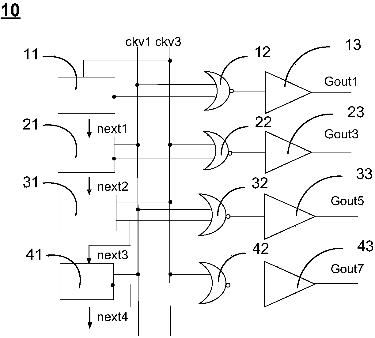
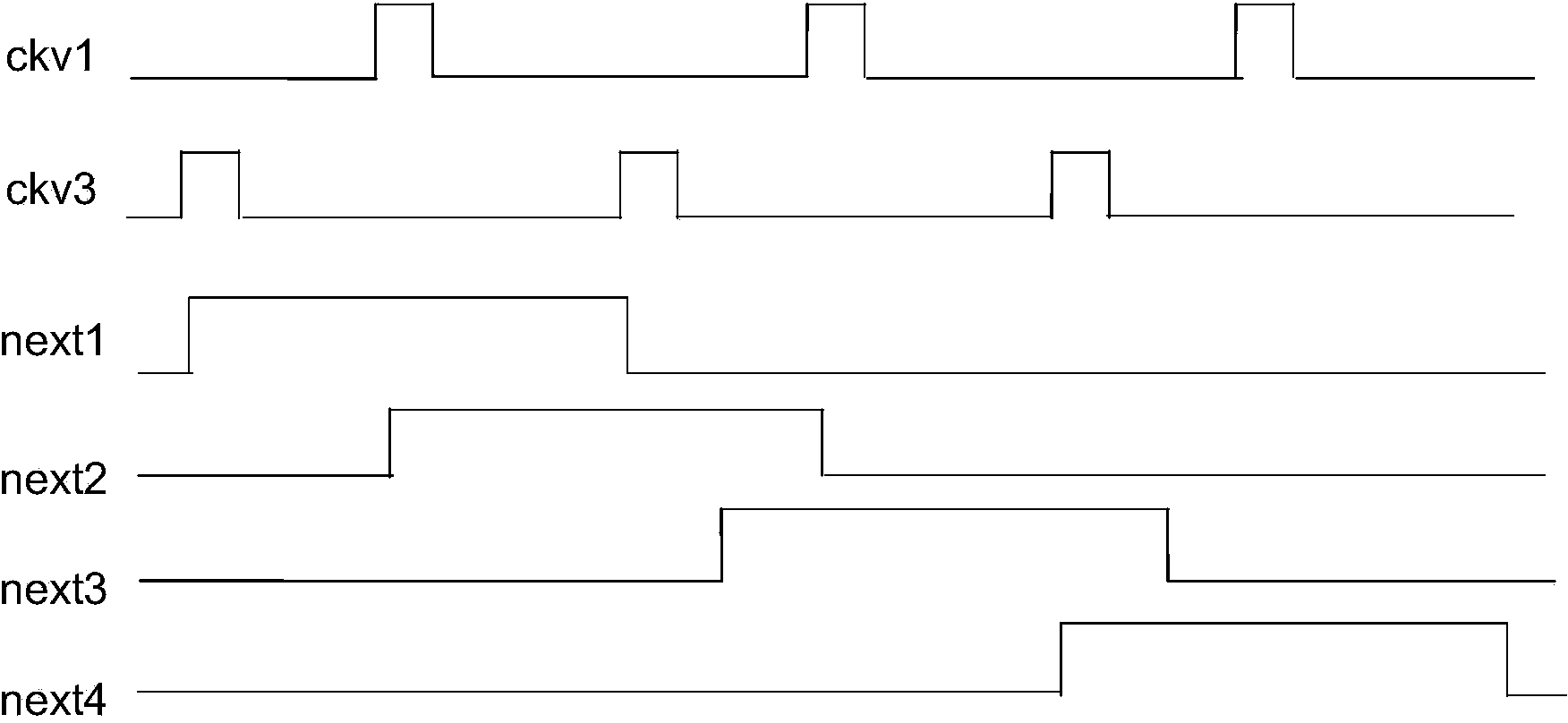
[0027] The gate drive circuit, its control method and liquid crystal display proposed by the present invention will be further described in detail below in conjunction with the accompanying drawings and specific embodiments. Advantages and features of the present invention will be apparent from the following description and claims. It should be noted that all the drawings are in a very simplified form and use imprecise scales, and are only used to facilitate and clearly assist the purpose of illustrating the embodiments of the present invention.

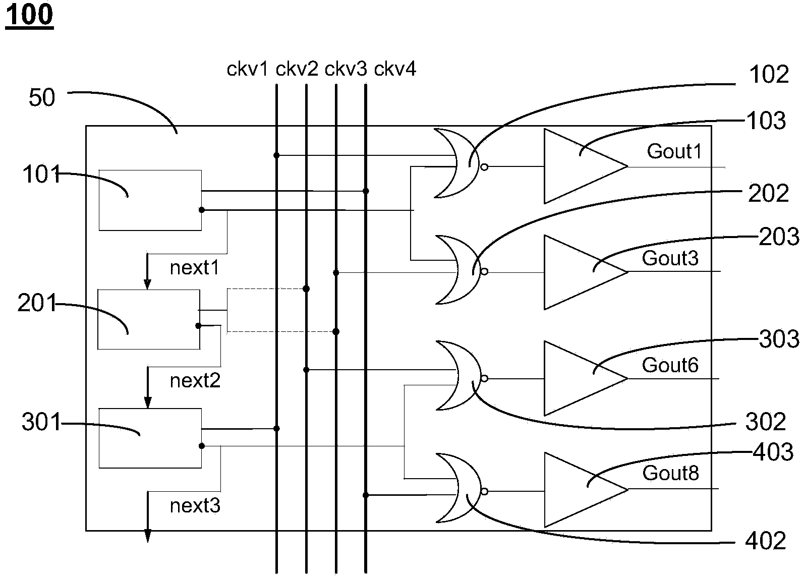
[0028] Please refer to image 3 , which is a partial structural block diagram of the gate driving circuit of the embodiment of the present invention. Such as image 3 As shown, the gate drive circuit 100 includes: a plurality of shift register units 50; the shift register unit 50 includes a first latch 101, a second latch 201, a third latch 301, a One NAND gate 102, the second NAND gate 202, the third NAND gate 302 and the fourth ...


PUM


Abstract

The invention provides a grid driving circuit and a control method thereof, and a liquid crystal display. The grid driving circuit comprises multiple shift register units. The shift register units comprise first latch registers, second latch registers, third latch registers, first NAND circuits, second NAND circuits, third NAND circuits and fourth NAND circuits. The output ends of the first latch registers are respectively connected with the input ends of the first NAND circuits and the input ends of the second NAND circuits; the output ends of the third latch registers are respectively connected with the input ends of the third NAND circuits and the input ends of the fourth NAND circuits; the input ends of the second latch registers are connected with the output ends of the first latch registers, and the output ends of the second latch registers are connected with the input ends of the third latch registers; and the shift register units are successively connected, and the output end of the third latch register of a previous shift register unit is connected with the input end of the first latch register of a later shift register unit.

Description

technical field [0001] The invention relates to the technical field of liquid crystal displays, in particular to a gate drive circuit, a control method thereof, and a liquid crystal display. Background technique [0002] With the development of semiconductor technology, flat panel display products are also emerging. Among many flat panel displays, Liquid Crystal Display (LCD) has become the mainstream of display products due to its advantages of low power consumption, low radiation, light weight and small size. [0003] A liquid crystal display generally includes a source drive circuit, a gate drive circuit, and a liquid crystal display panel. The liquid crystal display panel generally includes M scan lines and N data lines, and each row (column) of scan lines is connected to all of the same row (column). Pixels, each column (row) data line connects all pixels in the same column (row), M scanning lines correspond to M rows (columns) of pixels, N data lines correspond to N c...

Claims


Application Information

Patent Timeline
Patent Type & Authority Applications(China)
IPC IPC(8): G09G3/36
Inventor 庄杰
Owner XIAMEN TIANMA MICRO ELECTRONICS
Why Eureka
Try Eureka