Dual capacitively coupled coaxial cable to air microstrip transition

A technology of coaxial cable and switching device, applied in the field of RF signal transmission

Active Publication Date: 2014-08-13
COMMSCOPE TECH LLC
View PDF4 Cites 5 Cited by
  • Summary
  • Abstract
  • Description
  • Claims
  • Application Information

AI Technical Summary

Problems solved by technology

However aluminum is not acceptable for solder applications

Method used


Image

  • Dual capacitively coupled coaxial cable to air microstrip transition
  • Dual capacitively coupled coaxial cable to air microstrip transition
  • Dual capacitively coupled coaxial cable to air microstrip transition

Examples


Embodiment Construction

[0017] While the invention is susceptible to many different forms of embodiment, which are shown in the drawings and described herein in detail, it is to be understood that this disclosure is considered as illustrative of the principles of the invention, not as It is intended that the invention be limited to specific illustrated embodiments.

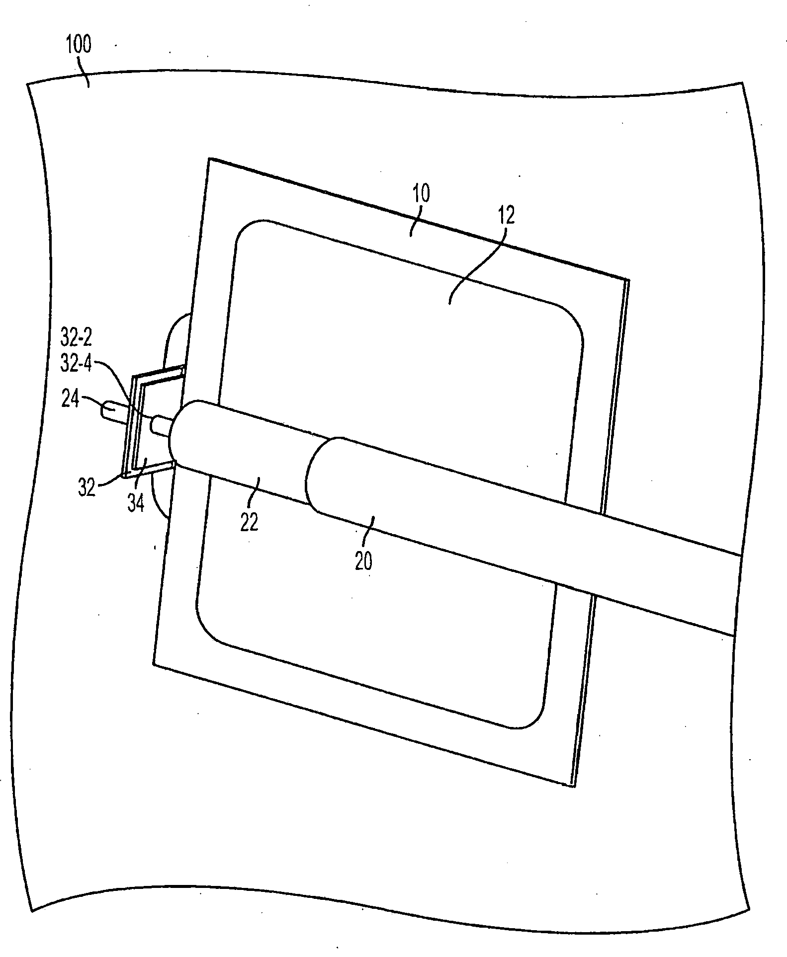
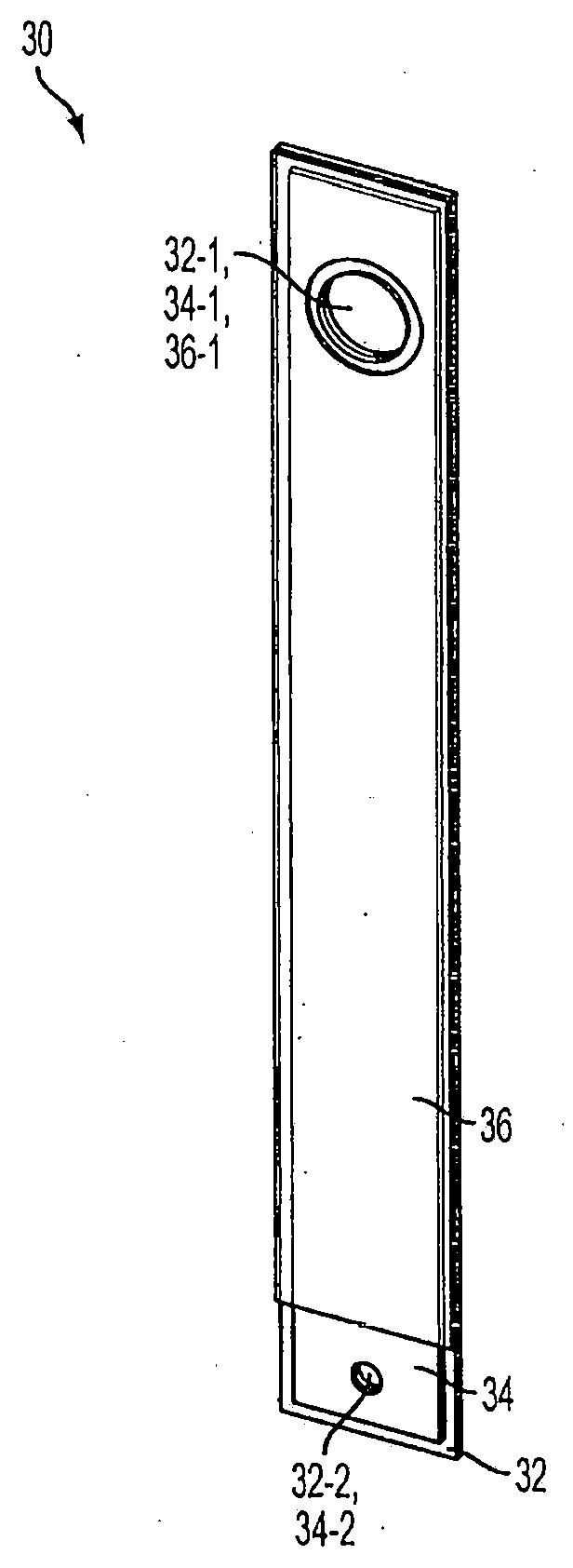
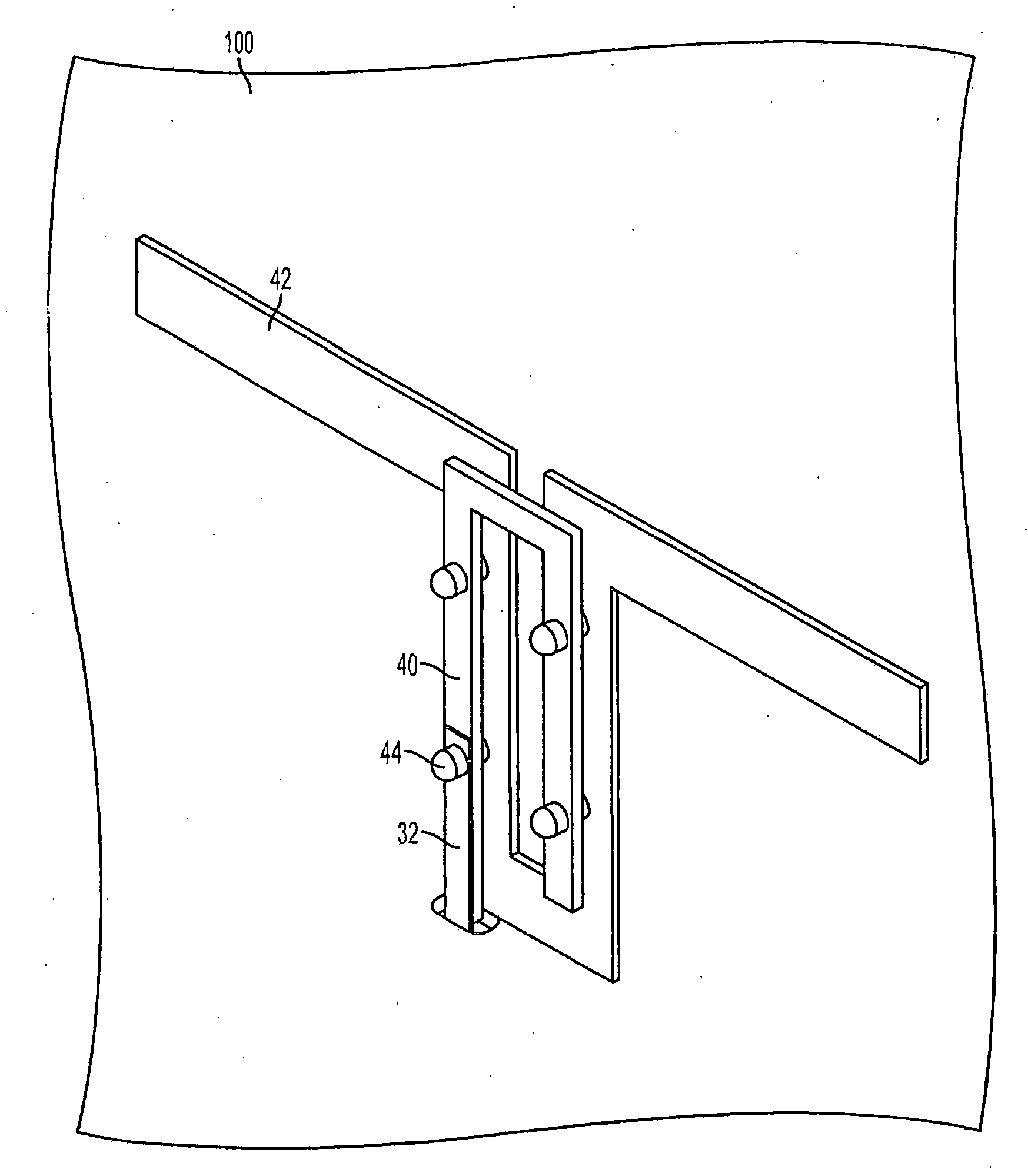
[0018] Embodiments disclosed herein include a transition device that couples RF energy between a coaxial cable transmission line conductor and a microstrip transmission line conductor with no or minimal metal-to-metal contact. For example, interposers disclosed herein may include one or more conductive surfaces that are partially or fully coated with one or more insulating materials. The insulating surface secures the coaxial cable conductor to the microstrip conductor in close proximity while also preventing direct metal-to-metal contact between the coaxial cable conductor and the microstrip conductor. Some embodiments disclosed herein...


PUM


Abstract

A transmission line transition that couples RF energy between a coaxial cable and an air dielectric microstrip is provided. In some embodiments, the transition can combine a thin printed circuit board substrate and an insulating surface to form an effective capacitive coupling transition that can couple RF energy from the center conductor of a coaxial cable to an air microstrip. In some embodiments, the transition can include an insulating system affixed to a metallic surface, and the insulating system can secure an airstrip conductor in close proximity to an inner conductor of a coaxial cable to capacitively couple the airstrip conductor to the inner conductor of the coaxial cable. In some embodiments, the transition can employ a metallic body coated with an insulating surface to capacitively couple RF energy from the center conductor of the coaxial cable to the air microstrip.

Description

technical field [0001] The present invention generally relates to RF signal transmission. More specifically, the present invention relates to a dual capacitively coupled coaxial cable to air microstrip transition device. Background technique [0002] In many base station antennas, several types of radio frequency (RF) transmission lines typically need to be incorporated in the signal path from the antenna input connector to the antenna radiating element. For example, electrical signal paths in base station antennas may include various combinations of coaxial cables, printed circuit board microstrips, and air electrolyte microstrips. [0003] When different types of transmission lines are connected to each other, the signal moves from the first transmission line to the second transmission line. In these connections, it is critical to maintain the transmission line impedance and avoid and / or minimize the introduction of passive intermodulation (PIM). [0004] Also, many kno...

Claims


Application Information

Patent Timeline
Patent Type & Authority Applications(China)
IPC IPC(8): H01P5/08
CPCH01P5/028H01Q9/16H01P5/085H01Q9/285
Inventor M·F·邦克兹科
Owner COMMSCOPE TECH LLC
Why Eureka
Try Eureka